Pole iron drive device

A driving device, permanent magnet technology, applied in the directions of generators/motors, electrical components, etc., can solve the problems of slow movement speed and high power consumption, and achieve the effect of saving electric energy

Active Publication Date: 2016-05-04
刘文华
View PDF5 Cites 3 Cited by
  • Summary
  • Abstract
  • Description
  • Claims
  • Application Information

AI Technical Summary

Problems solved by technology

[0003] Aiming at the problems of large power consumption and slow movement speed when the existing driving device is driven by a motor, the present invention provides an extremely iron driving device

Method used


Image

  • Pole iron drive device
  • Pole iron drive device
  • Pole iron drive device

Examples


Embodiment Construction

[0045] The specific embodiment that the present invention provides is described in further detail below in conjunction with accompanying drawing:

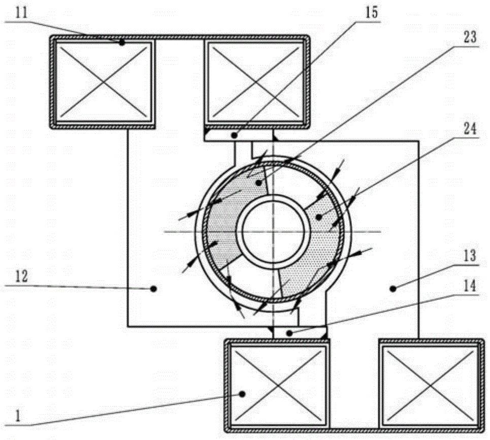
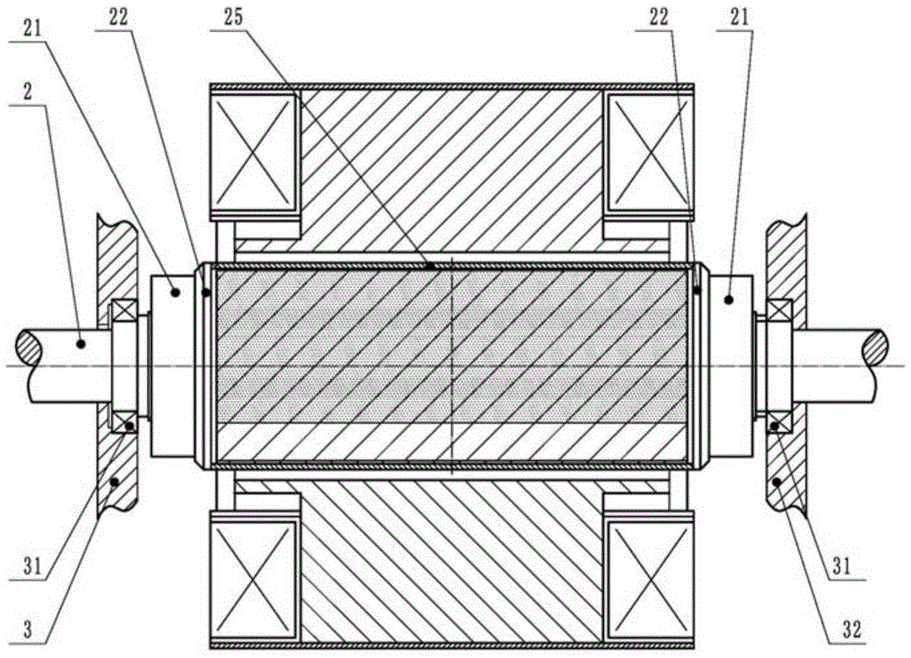
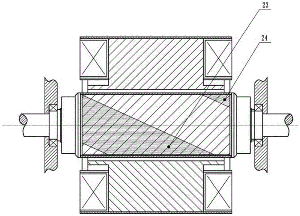
[0046] As shown in Fig. 1 (a), (b), be the structural representation of the first embodiment of the present invention, the device of this embodiment comprises:

[0047] The first component includes a first coil 1 and a second coil 11, a first pole iron 12, a second pole iron 13, a first connecting piece 14, and a second connecting piece 15, the first coil 1 and the second coil 11 Installed on both sides of the vertical center line and on the opposite side of the horizontal center line respectively, the diagonally separated first pole iron 12 and the second pole iron 13 are installed on the outside of the wall of the protruding iron, and the section of the protruding iron can be Rectangular, square, elliptical or circular, the first pole iron 12 and the second pole iron 13 are located below the bottom sides of the first coil 1 and t...


PUM


Abstract

The invention discloses a pole iron drive device, which comprises a first component and a second component, wherein the first component comprises pole iron and coils; each pole iron is separate or combined; one end of each pole iron is wound with the corresponding coil; the second component comprises a main shaft and permanent magnets; the permanent magnet are arranged at the outer side of the main shaft; each pole iron is arranged at the outer side of the corresponding permanent magnet; and when pulse currents are applied to the coils in the first component, generated magnetons release beam-excited magnetic fields through the separate pole iron or the combined pole iron, act on the permanent magnets and generate acting force to drive the second component to rotate. When same-direction currents are introduced into the coils, formed homoplar magnetic fields and the permanent magnets arranged at an N pole and an S pole simultaneously generate pick-up acting force and repellant acting force in one direction at different positions, so that the permanent magnets drive the main shaft to move.

Description

technical field [0001] The invention belongs to the technical field of low-voltage electrical appliances, and in particular relates to a separate or integrated pole iron driving device. Background technique [0002] At present, in mechanical motion, any reciprocating mechanical motion structure that requires relatively high power is basically implemented by a motor with a complex structure to drive the cam or a hydraulic or pneumatic type. Due to the power consumption of the motor driven Large and slow movement, driven by hydraulic pressure or air pressure, after a long period of repeated movement, its accuracy rate will be greatly reduced, and it is difficult to keep up with the rapid development of modernization. Contents of the invention [0003] Aiming at the problems of large power consumption and slow movement speed when the existing driving device is driven by a motor, the present invention provides an extremely iron driving device. [0004] Technical scheme of the...

Claims


Application Information

Patent Timeline
Patent Type & Authority Applications(China)
IPC IPC(8): H02N11/00
CPCH02N11/006
Inventor 刘文华刘焘刘旸李崇辉
Owner 刘文华
Why Eureka
Try Eureka