Linear vibration motor

A linear vibration and motor technology, applied in electromechanical devices, electrical components, etc., can solve the problems of small size and weight of mass blocks, reduce the low frequency performance of the motor, restrict the overall performance of the motor, etc., so as to increase the mass, improve the low frequency performance, and save vibration. effect of space

Active Publication Date: 2016-05-04
GOERTEK INC
View PDF5 Cites 13 Cited by
  • Summary
  • Abstract
  • Description
  • Claims
  • Application Information

AI Technical Summary

Problems solved by technology

An important defect of this type of elastic support is that it occupies a large vibration space of the vibrator in the vibration direction, which limits the volume of the mass block in the vibrator, resulting in a smaller volume and weight of the mass block, thereby increasing the motor. The resonant frequency reduces the low-frequency performance of the motor, which seriously restricts the improvement of the overall performance of the motor

Method used


Image

  • Linear vibration motor
  • Linear vibration motor
  • Linear vibration motor

Examples


Embodiment 1

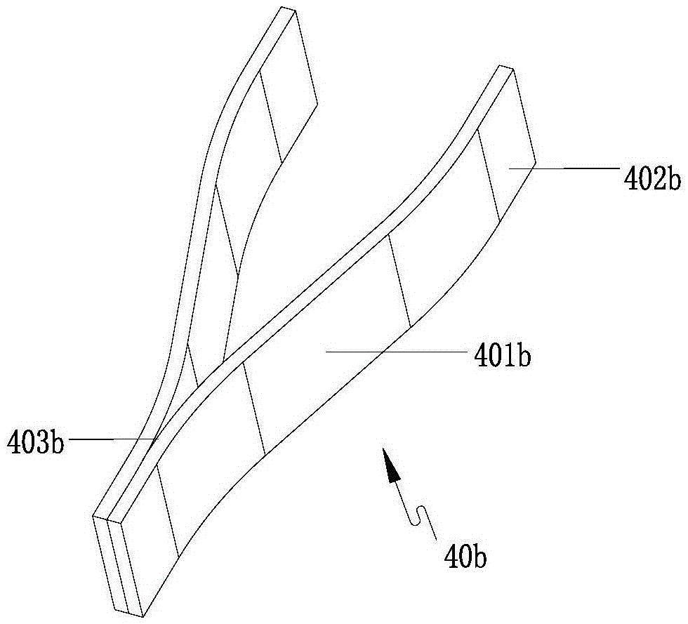
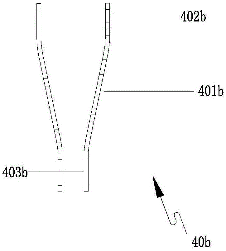
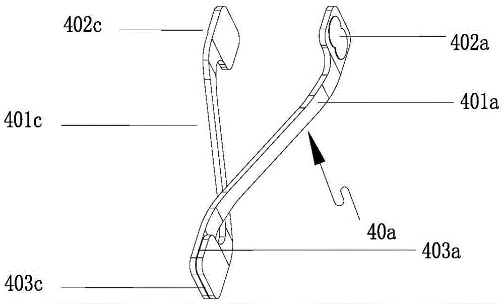
[0036] like Figure 5 and Figure 6 Commonly shown, a linear vibration motor is a cuboid structure, including a housing, a stator, a vibrator 20 and elastic supports 40a located at both ends of the vibrator 20 for supporting the vibrator and providing elastic restoring force. The housing includes an upper shell 10 and a lower shell 12 combined together, the upper shell 10 is a box-like structure with one end open, the lower shell 12 is a plate-like structure, and the open end of the upper shell 10 is buckled on the lower shell 12 , the stator is fixed on the lower case 12, and the vibrator 20 is suspended in the space enclosed by the upper case 10 and the lower case 12 through the elastic support member 40a.

[0037] like Figure 5 and Figure 6As shown together, the vibrator 20 includes a mass block 24. Two installation cavities are arranged side by side at the center of the mass block 24. A permanent magnet 26 is fixed in each installation cavity. The side of the mass blo...

Embodiment 2

[0048] This embodiment is basically the same as Embodiment 1, the difference is that:

[0049] Such as Figure 7 , Figure 8 and Figure 9 As shown together, two elastic supports 40a are provided at both ends of the vibrator. The two elastic supports 40a have the same structure and are stacked up and down. One elastic support 40a of the two elastic supports 40a located at the same end of the vibrator The state is the state after the other elastic support member 40a is flipped 180° around the central axis, which is the central axis parallel to the vibration direction of the vibrator.

[0050] Such as Figure 7 As shown, three installation cavities are arranged side by side in the middle of the mass block 24 in this embodiment, and a permanent magnet 26 is fixed in each installation cavity. The stator of this embodiment includes two coils 30 arranged side by side, and the two coils 30 are fixed inside the lower case 12 through one FPCB 50 .

[0051] Compared with Example 1,...


PUM


Abstract

The invention discloses a linear vibration motor, and relates to the technical field of miniature motors. The linear vibration motor comprises a shell, a stator, a vibrator and elastic support elements, wherein the elastic support elements are located at two ends of the vibrator and provide elastic restoring force; each elastic support element comprises two elastic arms; connection parts are arranged at two ends of the same side of each elastic arm respectively; two connection parts at one end of every two elastic arms are combined with each other; two elastic arms extend towards the corresponding directions of respective connection parts to form a transverse crossover structure in the transverse direction respectively; and two connection parts at the other ends of every two elastic arms are combined with the vibration and the shell respectively. A vibration space, occupied by the elastic support elements in the linear vibration motor, of the vibrator is relatively small; and an enough space is left for increase of the weight and the volume of a vibrator mass block, so that the resonant frequency of the vibration motor can be effectively reduced; the low-frequency performance of the vibration motor is improved; and the overall performance of the vibration motor is relatively high.

Description

technical field [0001] The invention relates to the technical field of micro motors, in particular to a linear vibration motor. Background technique [0002] Linear vibration motor is a kind of motor, its vibration direction is horizontal, and it is mostly used in portable electronic products, such as mobile phones, handheld game consoles and handheld multimedia entertainment equipment. A linear vibration motor usually includes a housing, a stator, and a vibrator. The stator includes a coil fixed on the housing. The vibrator includes a permanent magnet corresponding to the coil in the vertical direction and a mass block fixed with the permanent magnet. The motor also includes an elastic The supporting member and the elastic supporting member are respectively arranged at both ends of the vibrator, and are used to support the vibrator and provide elastic recovery force in the horizontal direction. [0003] Most of the existing elastic supports are shrapnel or springs. Usually...

Claims


Application Information

Patent Timeline
Patent Type & Authority Applications(China)
IPC IPC(8): H02K33/02
CPCH02K33/02H02K33/06H02K33/18
Inventor 朱跃光刘宝玉李云成
Owner GOERTEK INC
Why Eureka
Try Eureka