
Wearable electronic equipment charging control method and device, and intelligent watch

A charging control method and technology of electronic equipment, applied in the field of smart watches, can solve the problems of high heating temperature, high cost, and long charging time, and achieve the effects of prolonging battery life, low cost, and shortening charging time

Active Publication Date: 2016-05-04
GOERTEK INC
View PDF5 Cites 40 Cited by
  • Summary
  • Abstract
  • Description
  • Claims
  • Application Information

AI Technical Summary

Problems solved by technology

[0005] In order to solve the above problems, the present invention provides a charging control method, device and smart watch of a wearable electronic device, which solves the problem of excessive temperature caused by heat generation in the wireless charging process of the wearable device, and at the same time avoids the traditional means of charging The problem of long charging time and high cost caused by lowering the temperature

Method used


Image

  • Wearable electronic equipment charging control method and device, and intelligent watch
  • Wearable electronic equipment charging control method and device, and intelligent watch
  • Wearable electronic equipment charging control method and device, and intelligent watch

Examples


Embodiment 1

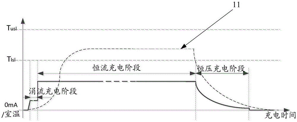
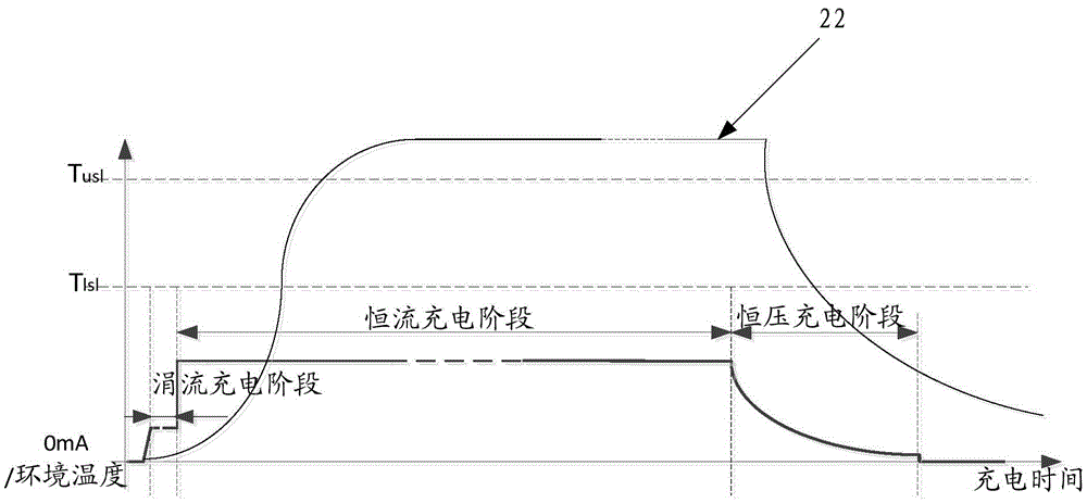
[0079] Figure 5 It is a schematic diagram of the lithium battery charging curve provided by another embodiment of the present invention under a higher ambient temperature or a poor heat dissipation environment, see Figure 5 , in this embodiment, it is illustrated that the control reduces the charging current value of the wearable electronic device once. Specifically, the current level of flow reduction control coefficient currently used is the first level of flow reduction control coefficient C1 (C1 is a value less than 1), and the currently used flow reduction control command is generated according to the first level of flow reduction control coefficient C1 (the second The product value of the first-level current reduction control coefficient and the set constant current charging current value is set in the currently used current reduction control command to indicate that the charging current value after the current level reduction current value is the product value); the c...

Embodiment 2

[0084] Figure 6 It is a schematic diagram of the lithium battery charging curve provided by another embodiment of the present invention in a higher ambient temperature or in an environment with poor heat dissipation. If the temperature of the smart watch is still not less than or equal to the lower limit of the temperature range after the first level of current reduction control measures are taken, And the set timer time has been reached, then take further flow reduction control measures to further reduce the charging current of the smart watch and thereby reduce the temperature value. In this embodiment, when the temperature is lowered by two-stage flow reduction control means, the situation that the two-stage flow reduction control means presents a progressive relationship is shown. It can be understood that if the temperature value of the lithium battery of the smart watch has dropped to less than or equal to the lower limit of the temperature range when the time reaches t...

Embodiment 3

[0088] Figure 7 It is the lithium battery charging curve provided by another embodiment of the present invention at a higher ambient temperature or in an environment with poor heat dissipation. The situation of the progressive relationship between them. It can be understood that if the temperature value of the lithium battery of the smart watch has dropped to less than or equal to the lower limit of the temperature range when the time reaches the currently set time threshold after one or two levels of current reduction control, the second or two levels can be omitted. The third level of downflow control measures.

[0089] see Figure 7 The change curve of charging time and temperature of the smart watch in 77, when the lithium battery of the smart watch is in the trickle charging stage, the temperature is low, when the charging current value of the lithium battery of the smart watch rises to the set constant current charging current value That is, when I=Icc, the temperatu...


PUM


Abstract

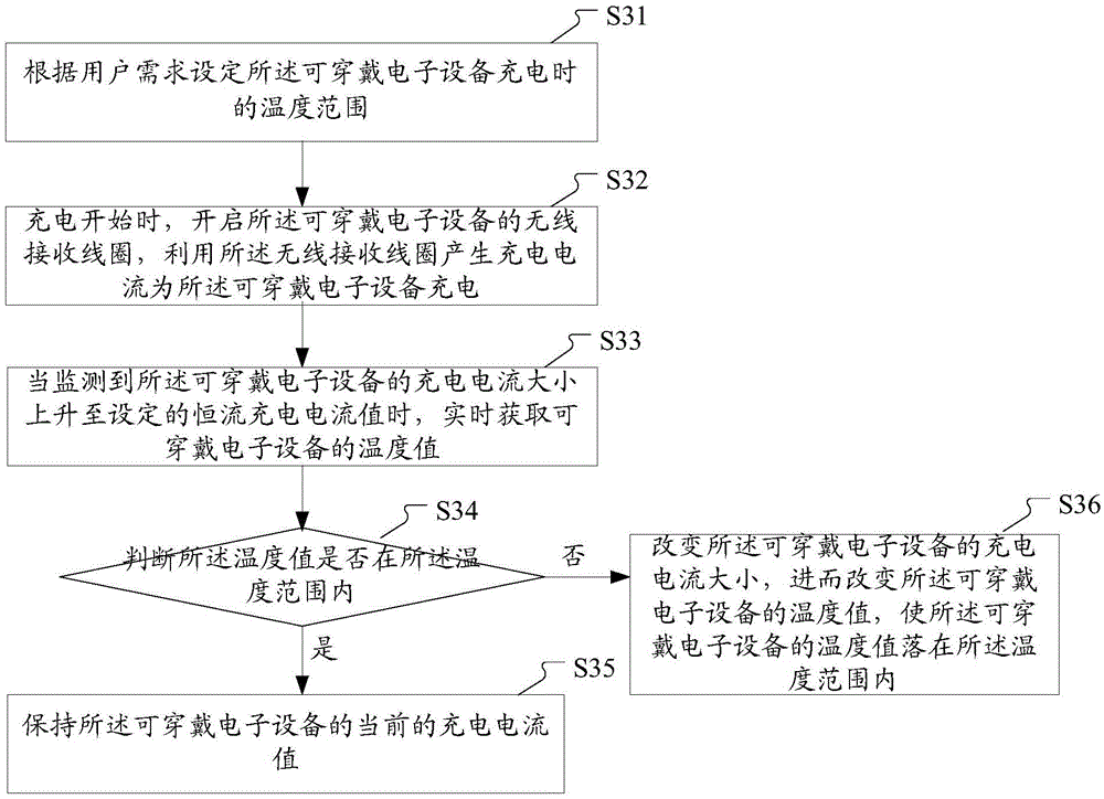
The invention discloses a wearable electronic equipment charging control method and device, and an intelligent watch. The method comprises the steps: setting a temperature range according to the demand of a user during the charging of wearable electronic equipment; starting a wireless receiving coil of the wearable electronic equipment when the charging is started, and generating a charging current through the wireless receiving coil, wherein the charging current can be used for charging the wearable electronic equipment; obtaining the temperature value of the wearable electronic equipment in real time when the charging current of the wearable electronic equipment is monitored to rise to a set constant-current charging current value; judging whether the temperature value is within the temperature range or not: maintaining the current charging current value of the wearable electronic equipment if the temperature value is within the temperature range, or else, charging the current charging current value of the wearable electronic equipment and enabling the temperature value of the wearable electronic equipment to be within the temperature range. According to the embodiment of the invention, the technical scheme solves a problem of overtemperature caused by heating in a wireless charging process of the wearable electronic equipment, and also solves a problem of too long charging time caused by the stopping of the charging for reducing the temperature in the prior art.

Description

technical field [0001] The present invention relates to the technical field of wearable electronic equipment, in particular to a charging control method and device for wearable electronic equipment and a smart watch. Background technique [0002] The wireless charging technology in the field of consumer electronics is mainly based on the WPC (Qi) standard. Qi is the world's first standardization organization to promote wireless charging technology - the "wireless charging" standard launched by the Wireless Power Consortium (WPC), which is convenient and universal. The Qi standard adopts "electromagnetic induction technology". The charging efficiency of the wireless charging method based on "electromagnetic induction technology" is positively related to the power of the device. Wearable electronic devices (such as smart watches) usually have a small battery capacity due to the size limitation of the device, so the power is not large, which leads to low charging efficiency wh...

Claims


Application Information

Patent Timeline
IPC IPC(8): H02J7/00H01M10/44H01M10/615H01M10/623
CPCH01M10/443H02J7/0036H02J2310/22H02J50/10H02J7/00309H01M10/44H01M10/448H02J7/0042G04G19/06H01M2220/30H02J7/007194Y02E60/10H02J7/04H01M10/623H01M10/4257H01M10/0525H02J7/0047H02J7/00712H02J7/0031H02J50/005G04G9/007H02J7/007192
Inventor 孟昕曹焕杰候泽男李兴华
Owner GOERTEK INC
Learn More