
Measuring method of compound deformation field of tension-compression and bending of variable cross-section beam structure

A technology of variable cross-section beams and bending deformation, applied in the direction of measuring devices, instruments, etc., can solve the problems of easy deformation of benchmarks, difficulty in establishing benchmarks, and limited measurement points, and achieve the effect of broadening the measurement field and easy operation

Inactive Publication Date: 2019-01-04
WUHAN UNIV OF TECH
View PDF4 Cites 0 Cited by
  • Summary
  • Abstract
  • Description
  • Claims
  • Application Information

AI Technical Summary

Problems solved by technology

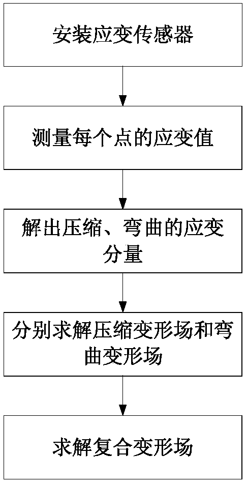
[0007] Aiming at the problems in the prior art, the present invention provides a method for measuring the combined tension, compression and bending deformation field of a variable cross-section beam structure, which effectively solves the problems in the existing measurement technology that it is difficult to establish a benchmark, the benchmark is easily deformed, and the measurement points are limited The problem

Method used


Image

  • Measuring method of compound deformation field of tension-compression and bending of variable cross-section beam structure
  • Measuring method of compound deformation field of tension-compression and bending of variable cross-section beam structure
  • Measuring method of compound deformation field of tension-compression and bending of variable cross-section beam structure

Examples


Embodiment 2

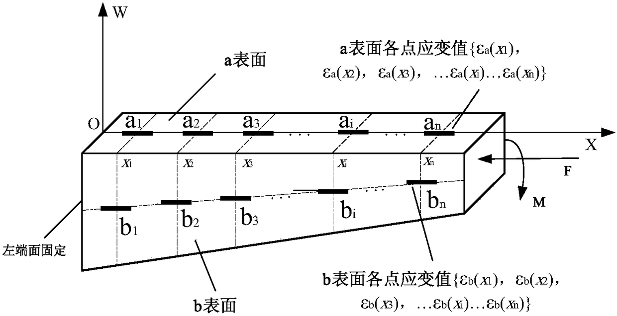
[0028] In the second embodiment, when measuring the deformation of the variable-section column of the machine tool, after the variable-section column of the machine tool is subjected to tensile compression deformation and bending deformation at the same time, the selected measurement surface is as follows Figure 5 shown.

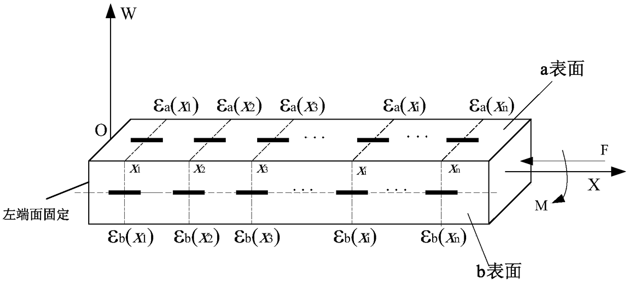
[0029] Among them, the first step is to install the displacement sensor on the surface of the variable-section column of the machine tool. First, a rectangular coordinate system must be established on the plane where the variable-section beam structure bends, and the vertical direction is taken as the x-axis, as shown in Figure 5 As shown, a w-axis is established at one end of the beam perpendicular to the x-axis (ie, the bending direction); Layer positions correspond to the same number of strain sensors installed, which are denoted as {α 1 , a 2 , a i ,...α n} and {b 1 , b 2 , b i ,... b n}, where {a 1 , a 2 , a i ,...a n} means to install {x ...


PUM


Abstract

The invention discloses a method for measuring a pull-press and bending composite deformation field of a variable cross section beam structure. In this method, a pure bending strain of a bent surface of a to-be-measured structure is the different between a composite strain, caused by the pulling or pressing of a bent surface a in an x direction and the bending deformation in a w direction, and the pulling or pressing deformation of a neutral layer of the structure on a side surface b. The method comprises the steps: firstly solving the pure bending deformation of the surface a of the structure at the position of a strain sensor and the pulling or pressing strain of the side surface a according to strain values, measured by the strain sensor, of the surface a and the side surface b; secondly respectively solving the pulling or pressing deformation and bending information of the two surfaces at the position of the strain sensor according to the theories of mathematic integration and displacement; and finally solving the composite deformation field of the structure through employing the two types of deformation. The method effectively solves problems in the prior art that a reference is difficult to set, the reference is liable to deform, and a measurement is limited.

Description

technical field [0001] The invention belongs to a measurement method of a variable-section beam structure, in particular to a measurement method of the tension-compression and bending compound deformation field of the variable-section beam structure. Background technique [0002] With the rapid development of modern industrial science and technology, there is an increasing pursuit of high quality, high precision, high efficiency and high intelligence in the mechanical manufacturing process. At the current stage of our country, whether it is railway construction, power station construction, shipbuilding, aerospace construction, or automobile, engineering machinery, and military industries, a large number of high-end machine tools are needed to support them. As far as the current situation is concerned, the main factor that restricts the further improvement of the precision of heavy-duty CNC machine tools is the structural deformation of the machine tool. The deformation inclu...

Claims


Application Information

Patent Timeline
Patent Type & Authority Patents(China)
IPC IPC(8): G01B21/32
CPCG01B21/32
Inventor 刘明尧王丽娜李瑞亚刘慧
Owner WUHAN UNIV OF TECH
Learn More