
Initiation controller of electronic detonator and control method thereof

A technology of electronic detonators and controllers, which is applied to program control, electrical program control, and blasting in sequence/logic controllers, and can solve problems such as long charging time of electronic detonators, potential safety hazards, and illegal detonation

Inactive Publication Date: 2016-05-04
BEIJING INSTITUTE OF TECHNOLOGYGY
View PDF5 Cites 15 Cited by
  • Summary
  • Abstract
  • Description
  • Claims
  • Application Information

AI Technical Summary

Problems solved by technology

The traditional electronic detonator detonation controller does not verify the identity of the operator or only performs simple password verification. If the electronic detonator detonation controller is obtained illegally, the electronic detonator is easily detonated illegally, and there is a great potential safety hazard
At the same time, the current electronic detonator detonation controller does not limit the detonation time and position legality of the electronic detonator, which may also cause illegal detonation or mining at the specified time and position.
On the other hand, the function of the current electronic detonator detonation controller is not perfect, the steps of registering the electronic detonator are cumbersome, the operation of setting the delay time is relatively complicated, the charging time of the electronic detonator is long, and there are certain problems in the process of controlling the detonation. potential safety hazards, the human-computer interaction interface is relatively rough, resulting in a poor user experience

Method used


Image

  • Initiation controller of electronic detonator and control method thereof
  • Initiation controller of electronic detonator and control method thereof
  • Initiation controller of electronic detonator and control method thereof

Examples


Embodiment Construction

[0063] The present invention will be further described through the embodiments below in conjunction with the accompanying drawings.

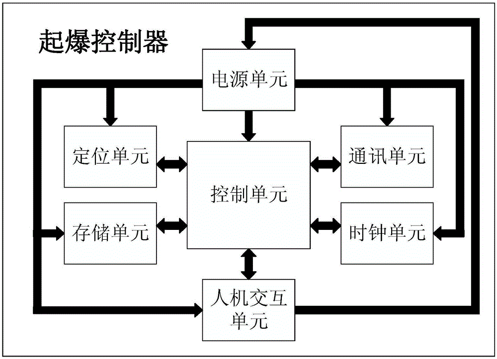
[0064] Such as figure 1 As shown, the detonation controller of the electronic detonator in this embodiment includes: a control unit, a power supply unit, a communication unit, a human-computer interaction unit, a clock unit, a positioning unit and a storage unit.

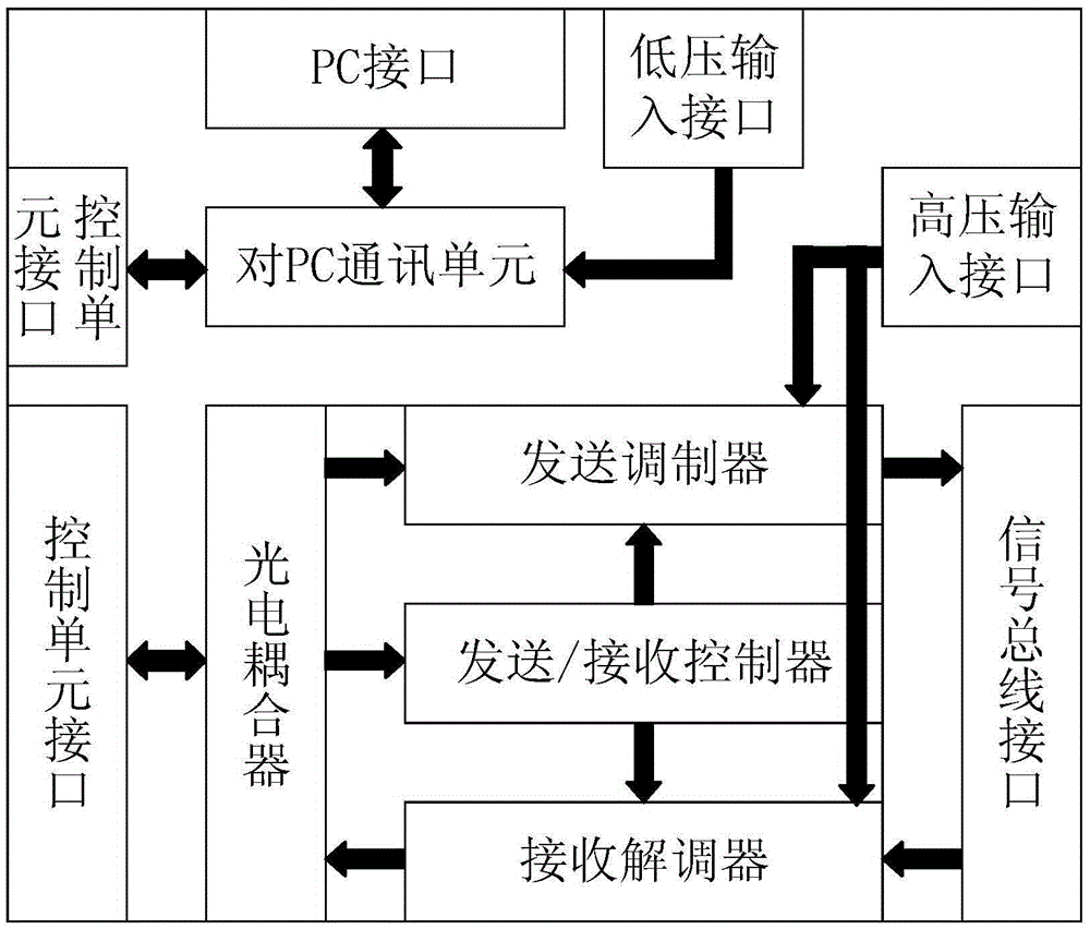
[0065] Such as figure 2 As shown, the power supply unit includes a built-in power supply, a step-down circuit and a boost circuit; wherein, the built-in power supply is connected to an external charging device through the charging terminal for charging, and is connected to the locking device of the human-computer interaction unit through the interface of the human-computer interaction module, Block the voltage output of the built-in power supply; the voltage input terminal of the step-down circuit is connected to the locking device of the human-computer interaction unit through the ...


PUM


Abstract

The invention discloses an initiation controller of an electronic detonator and a control method thereof. According to the initiation controller, a photoelectric coupler is used in a communication unit, so that electric signals are isolated, and the safety and reliability of communication are increased; the PC (Personal Computer) communication unit is used, so that two-way communication between the initiation controller and a PC is realized, and the blasting sequence is designed in advance by virtue of the PC, so that automatic setting is realized, thereby simplifying spot operation; a communication module of the electronic detonator is used, so that two-way communication between the initiation controller and the electronic detonator is realized, and accurate management and control of the initiation controller over the electronic detonator in an initiation process are guaranteed; an authorizing device and a locking device are used in a human-computer interaction unit for double insurance, so that the safety of the initiation controller is greatly increased; positioning information is obtained by a positioning unit on the basis of a Beidou positioning chip, so that the electronic detonator is accurately positioned, thereby guaranteeing an automatic setting function that the delay time is intelligently distributed according to position information of the electronic detonator.

Description

technical field [0001] The invention relates to the detonation technology of pyrotechnics, in particular to a detonation controller of an electronic detonator and a control method thereof. Background technique [0002] The existing electric detonator detonators generally use a series or series-parallel combination electric detonator network. When thousands of detonators are connected in series, in order to ensure that all the detonators in the network can detonate at the same time, the detonator detonator should be able to generate a current of one to several amperes instantaneously. There will be phenomena such as rejection of explosion and half explosion. The resistance of a single generator detonator is generally about one to several ohms, so the above-mentioned electric detonator detonator needs to have a boost circuit and be able to provide an output voltage of the order of kilovolts. Therefore, the above-mentioned electric detonator detonator has certain danger in us...

Claims


Application Information

Patent Timeline
IPC IPC(8): F42C19/12F42D1/045G05B19/04
CPCF42C19/12F42D1/045G05B19/04
Inventor 娄文忠郭云龙卢宇飞刘鹏丁旭冉
Owner BEIJING INSTITUTE OF TECHNOLOGYGY
Learn More