
Fan, its control method and device, and terminal equipment

A technology of terminal equipment and control methods, applied in mechanical equipment, lighting and heating equipment, heating and ventilation control systems, etc., can solve the problems of poor real-time performance of fan control, and achieve the effect of improving real-time performance

Active Publication Date: 2018-08-07
GREE ELECTRIC APPLIANCES INC
View PDF8 Cites 0 Cited by
  • Summary
  • Abstract
  • Description
  • Claims
  • Application Information

AI Technical Summary

Problems solved by technology

[0005] The main purpose of the present invention is to provide a fan and its control method and device and terminal equipment, so as to at least solve the problem of poor real-time control of the fan

Method used


Image

  • Fan, its control method and device, and terminal equipment
  • Fan, its control method and device, and terminal equipment
  • Fan, its control method and device, and terminal equipment

Examples


Embodiment Construction

[0034] It should be noted that, in the case of no conflict, the embodiments in the present application and the features in the embodiments can be combined with each other. The present invention will be described in detail below with reference to the accompanying drawings and examples.

[0035] In order to enable those skilled in the art to better understand the solution of the present application, the technical solution in the embodiment of the application will be clearly and completely described below in conjunction with the accompanying drawings in the embodiment of the application. Obviously, the described embodiment is only It is an embodiment of a part of the application, but not all of the embodiments. Based on the embodiments in this application, all other embodiments obtained by persons of ordinary skill in the art without creative efforts shall fall within the scope of protection of this application.

[0036] It should be noted that the terms "first" and "second" in ...


PUM


Abstract

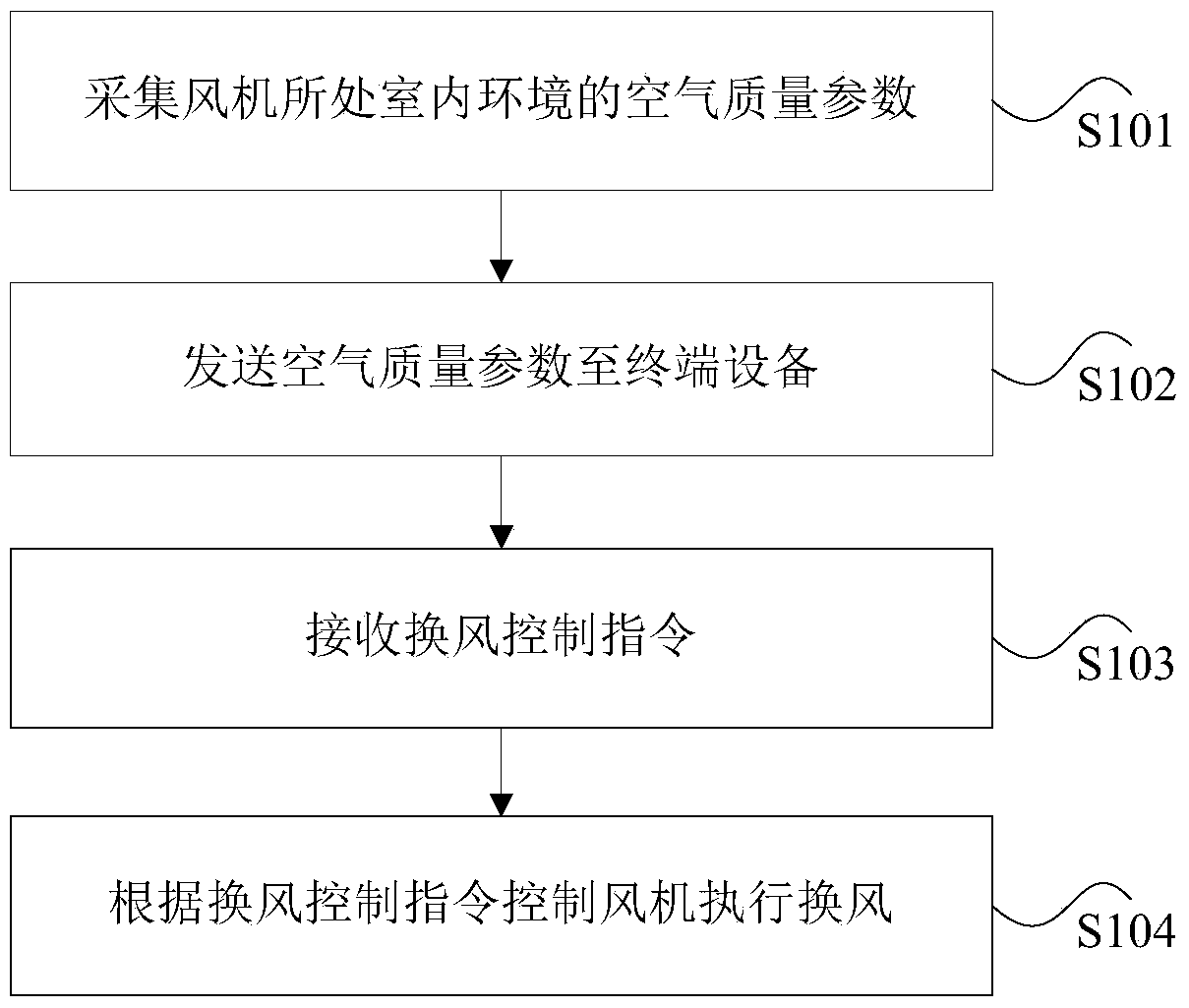
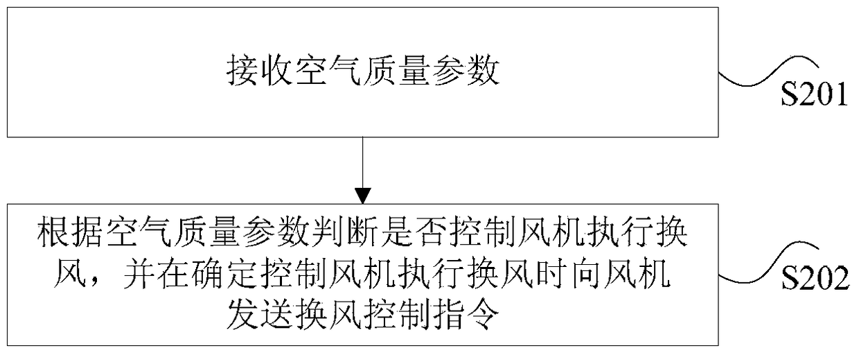
The invention discloses a fan, a control method and device thereof and a terminal device. The control method of the fan comprises the steps of collecting the air quality parameters of the indoor environment where the fan is located; sending the air quality parameters to the terminal device, wherein the terminal device is used for judging whether to control the fan to implement ventilation according to the air quality parameters and sending ventilation control instructions to the fan when the fan is to be controlled to implement ventilation; receiving the ventilation control instructions; controlling the fan to implement ventilation according to the ventilation control instructions. According to the method, the instantaneity of control over the fan is improved.

Description

technical field [0001] The present invention relates to the field of fans, in particular to a fan, its control method and device, and terminal equipment. Background technique [0002] Currently, devices with a ventilation function have a ventilation system, for example, an air conditioner capable of realizing the ventilation function. The air exchange system is composed of fans. Among them, most of the fans in the air exchange system simply change the air regularly and quantitatively, or artificially control the fan to turn on or off by operating the remote control of the equipment, and the real-time performance is relatively poor. [0003] Some fans are connected to a carbon dioxide sensor to detect the concentration in the air through the carbon dioxide sensor to control the opening or closing of the fan. However, this method only feeds back the detected carbon dioxide concentration to the main board of the fan, and then controls the opening or closing of the fan through...

Claims


Application Information

Patent Timeline
Patent Type & Authority Patents(China)
IPC IPC(8): F24F11/64F24F11/72F24F11/58F24F7/007F24F110/50
CPCF24F7/007F24F11/30F24F11/62F24F11/65F24F11/70F24F2110/50Y02B30/70
Inventor 蒋佳伟胡锐杨秀妹胡强
Owner GREE ELECTRIC APPLIANCES INC
Learn More