
Multifunctional air treatment integrated equipment

A technology of air treatment and integrated equipment, applied in the field of air conditioning, which can solve the problems of inconvenient installation, insufficient space to place indoor units, and small space, and achieve the effects of simple and convenient operation, space saving, and simple structure

Inactive Publication Date: 2016-05-04
周晓明
View PDF7 Cites 6 Cited by
  • Summary
  • Abstract
  • Description
  • Claims
  • Application Information

AI Technical Summary

Problems solved by technology

Especially in some special places of the family, such as kitchens, bathrooms, etc., the space of such places is relatively small, and there is not enough space to install indoor units; some families have installed kitchen air conditioners in the kitchen, but the existing kitchen air conditioners are installed separately. The main unit of the air conditioner is installed outdoors, and the auxiliary unit of the air conditioner is installed indoors. At this time, there are problems of inconvenient installation such as pipe routing and external hanging in the split configuration.
[0003] Some families have installed new fans in the bathroom separately to improve the air in the bathroom, but they cannot handle the temperature and humidity of the air; general bathroom lighting needs to install additional lamps, which takes up space
[0004] The existing air conditioner wire controller is cumbersome to operate, mode switching, and temperature setting, causing inconvenience to users

Method used


Image

  • Multifunctional air treatment integrated equipment
  • Multifunctional air treatment integrated equipment
  • Multifunctional air treatment integrated equipment

Examples


Embodiment Construction

[0018] In order to make the object, technical solution and advantages of the present invention clearer, the present invention will be further described below in conjunction with the accompanying drawings and specific embodiments. It should be understood that the specific embodiments described here are only used to explain the present invention, not to limit the present invention.

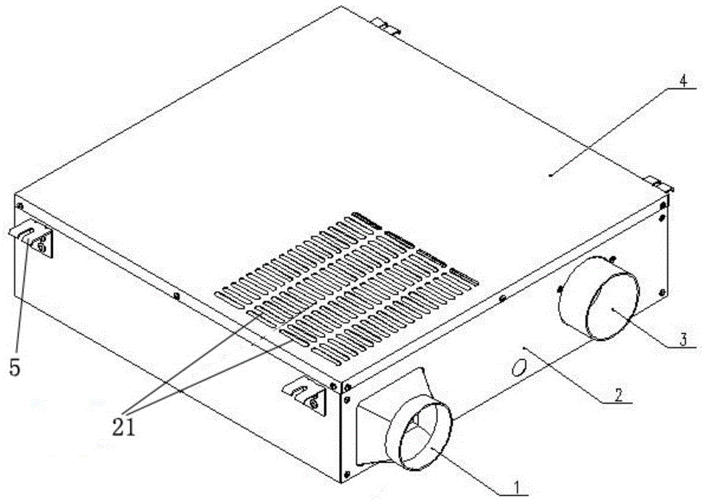
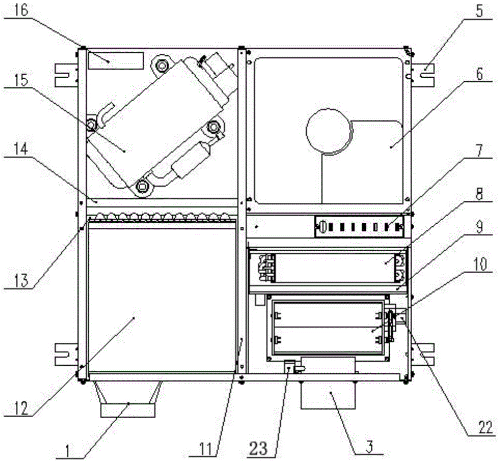
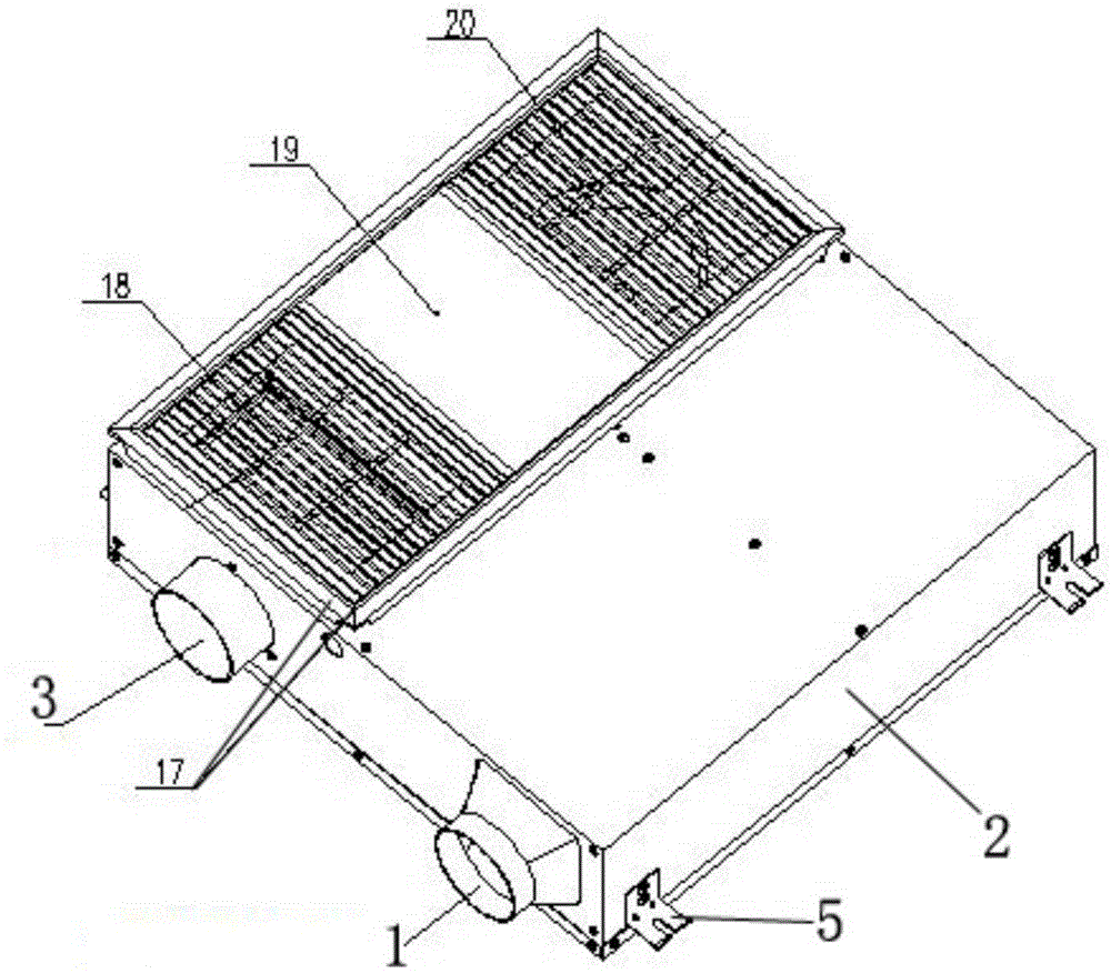
[0019] see Figure 1 to Figure 3 As shown, a multi-functional air treatment integrated device includes a lower casing 2, the lower casing 2 is divided into an evaporation cavity and a condensation cavity by a partition 11, and an evaporator 8 and a water storage tray are arranged in the evaporation cavity 9. The evaporating fan 6 and the PTC electric heating 7, the evaporator 8 is installed in the water accumulation tray 9, the evaporator 8 and the water accumulation tray 9 are connected and fixed by screws, and the water accumulation tray 9 is fixed in the evaporation chamber of the lower shell 2 b...


PUM


Abstract

The invention relates to multifunctional air treatment integrated equipment. The multifunctional air treatment integrated equipment comprises a lower shell. The lower shell is divided into an evaporation chamber and a condensation chamber through a partition plate. An evaporator, a water collector, an evaporation fan and a PTC electric heater are arranged in the evaporation chamber. The evaporator is installed in the water collector, and the evaporation fan and the PTC electric heater are installed on one side of the evaporator. A condenser, a condensation fan, a horizontal compressor and an electric appliance box are arranged in the condensation chamber. The condenser is arranged above the condensation fan, the horizontal compressor and the condenser are divided through a compressor partition plate, and the electric appliance box is arranged on one side of the horizontal compressor. Lighting, fresh air exchange, refrigeration, heating and other functions are integrated, a wall type drive-by-wire switch is adopted, operation is simple and convenient, and integrated design is adopted. The multifunctional air treatment integrated equipment is simple in structure, ultrathin and suitable for a suspended ceiling, saves space, and can well meet the requirement of practical application of human settlement.

Description

technical field [0001] The invention belongs to the technical field of air conditioning, and in particular relates to a multifunctional air treatment integrated device. Background technique [0002] With the gradual improvement of people's living standards, the requirements for the comfort of the environment are also getting higher and higher. Especially in some special places of the family, such as kitchens, bathrooms, etc., the space of such places is relatively small, and there is not enough space to install indoor units; some families have installed kitchen air conditioners in the kitchen, but the existing kitchen air conditioners are installed separately. The main unit of the air conditioner is installed outdoors, and the auxiliary unit of the air conditioner is installed indoors. At this time, there are problems of inconvenient installation such as pipe routing and external hanging in the split configuration. [0003] Some families have installed a new fan separately ...

Claims


Application Information

Patent Timeline
IPC IPC(8): F24F5/00F21V33/00F21Y115/10
CPCF21V33/0092F24F5/0035F24F2221/34
Inventor 周晓明
Owner 周晓明
Learn More