Light distribution lens and illuminating system adopting same
A light distribution lens and lens technology, applied in the field of lighting systems, can solve the problems of large optical aperture and optical height of the lens structure, difficulty in ensuring lighting effect, weak light control ability, etc., to simplify the structure, ensure the lighting effect of the design, and facilitate the design and the effect produced
- Summary
- Abstract
- Description
- Claims
- Application Information
AI Technical Summary
Problems solved by technology
Method used
Image
Examples
Embodiment 1
[0055] Embodiment 1: as figure 1 and 2 as shown,
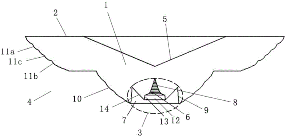
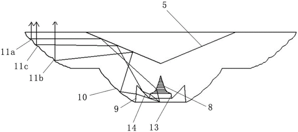
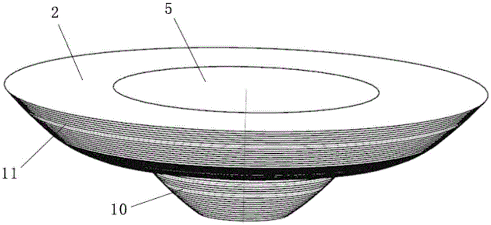
[0056] A light distribution lens, comprising a lens body 1, the lens body 1 is provided with a light exit area 2 and a central transmission area 3, and an outer ring reflection area 4 is also provided between the light exit area 2 and the central transmission area 3, The lens body 1 is also provided with a central reflection area 5, and the light emitted by the light source enters the lens body 1 from the central transmission area 3. Among the light emitted by the light source, the light in the central part is a small-angle light, and the light in the peripheral part of the light is a large angle. Angle rays, at least a part of small-angle rays enter the lens body 1 and irradiate on the central reflection area 5, then are reflected by the central reflection area 5 to the outer circle reflection area 4, and then are reflected by the outer circle reflection area 4 to The light exit area 2 is refracted out of the lens body 1 by...
Embodiment 2
[0060] Example 2, such as figure 1 and 2 as shown,
[0061] As in the light distribution lens described in Embodiment 1, the central transmission area 3 is divided into a first cavity 6 and a second cavity 7 along the central axis of the lens body 1, and the first cavity 6 is close to the light exit area 2. The second cavity 7 is close to the light source, the second cavity 7 surrounds the first cavity 6, the inner wall of the first cavity 6 is the first incident surface 8, the second The inner wall of the cavity 7 is the second incident surface 9 , the small-angle light is refracted into the lens body 1 from the first incident surface 8 , and the large-angle light is refracted into the lens body 1 from the second incident surface 9 .
[0062] In the above solution of this embodiment, the small-angle light and the large-angle light in the light emitted by the light source are controlled separately, which not only improves the control ability of the small-angle light, but als...
Embodiment 3
[0064] Example 3, such as figure 1 and2 as shown,
[0065] In the light distribution lens described in Embodiment 2, the outer reflective area 4 includes a first reflective area 10 and a second reflective area 11, the first reflective area 10 is close to the central transmissive area 3, and the second reflective area 11 is close to the light output area 2, the first reflection area 10 and the second reflection area form a stepped structure, at least a part of the small-angle light is refracted from the first incident surface 8 into the lens body 1, and then reflected by the central reflection area 5 to The second reflective area 11 is then reflected to the light exit area 2; at least a part of the large-angle light is refracted from the second incident surface 9 into the lens body 1 and then irradiated on the first reflective area 10, and then reflected by the first reflective area 10 to The central reflective area 5 is then reflected by the central reflective area 5 to the s...
PUM
 Abstract
Description
Claims
Application Information
 - Generate Ideas
- Intellectual Property
- Life Sciences
- Materials
- Tech Scout
- Unparalleled Data Quality
- Higher Quality Content
- 60% Fewer Hallucinations
Browse by: Latest US Patents, China's latest patents, Technical Efficacy Thesaurus, Application Domain, Technology Topic, Popular Technical Reports.
© 2025 PatSnap. All rights reserved.Legal|Privacy policy|Modern Slavery Act Transparency Statement|Sitemap|About US| Contact US: help@patsnap.com


