
Swing arm type feeding lifting mechanism

A swing arm type, feeding technology, applied in metal processing equipment, feeding devices, manufacturing tools, etc., can solve the problems of increasing equipment manufacturing cost, increasing equipment weight, large driving power, etc., reducing manufacturing cost and equipment weight. , The effect of the cylinder running without jamming

Inactive Publication Date: 2016-05-04
LIUZHOU GAOHUA MACHINE +1
View PDF5 Cites 3 Cited by
  • Summary
  • Abstract
  • Description
  • Claims
  • Application Information

AI Technical Summary

Problems solved by technology

In the stamping production line, the movement of the stamping robot on the Z axis is relatively simple compared with other axes, with fewer positioning points and relatively low precision requirements. Using servo motor drive will increase the manufacturing cost of the equipment and increase the cost of the equipment. weight, resulting in the need for greater drive power

Method used


Image

  • Swing arm type feeding lifting mechanism
  • Swing arm type feeding lifting mechanism
  • Swing arm type feeding lifting mechanism

Examples


Embodiment Construction

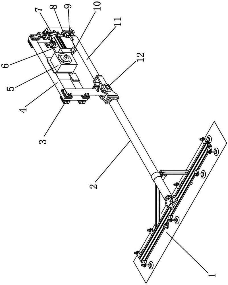
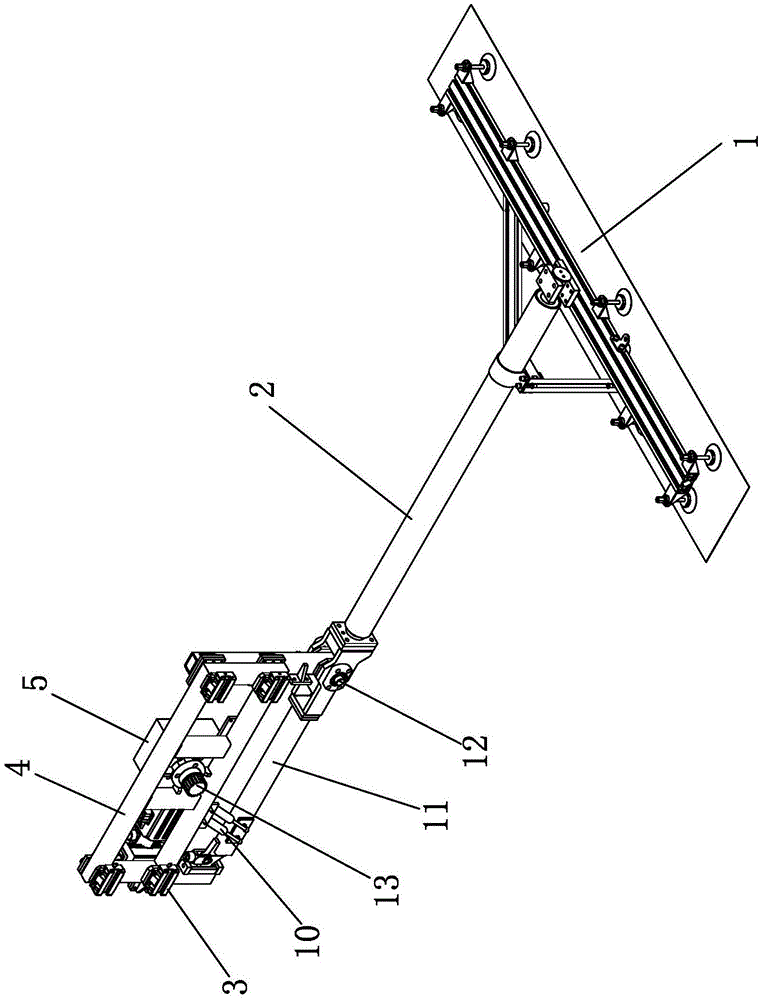
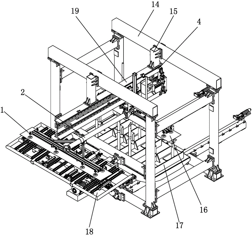
[0016] Such as figure 1 , figure 2 As shown, the swing arm type feeding and lifting mechanism of the present invention includes a moving frame 4, a swing arm and a feeding end picker 1, and the moving frame 4 is slidably connected to the X-axis moving guide rail 19. The X-axis moving guide rail 19 of the punching, destacking and loading robot is connected in the support frame 14 through the bracket 15. The X-axis moving guide rail 19 includes a guide rail installation beam, a slide rail and a rack, and the guide rail installation beam is connected in the support frame 14 through the bracket 15. . The slide rail is fixedly connected to one side of the guide rail installation beam in the X-axis direction, and the rack is fixedly connected to the guide rail installation beam and located at the side edge of the slide rail. Also be connected with motor 6 and reducer 5 on the moving frame 4, the output shaft of reducer 5 is connected with the gear 13 that meshes with the rack on ...


PUM


Abstract

The invention discloses a swing arm type feeding lifting mechanism, and relates to a feeding mechanism used in the field of machining. The swing arm type feeding lifting mechanism comprises a movable rack, a swing arm and a feeding tooling, wherein the movable rack is connected to an X-axis moving guide rail in a slidable manner; the swing arm is connected to the lower side of the movable rack in a swingable manner by a connecting shaft; the feeding tooling is connected to the front end of the swing arm; a cylinder for driving the swing arm to swing up and down is arranged at the rear end of the movable rack; the inside of the rear end of the movable rack is connected with a limiting mechanism for limiting the swing arm to excessively swing. The swing arm type feeding lifting mechanism disclosed by the invention is driven to move in a Z-axis direction by the cylinder, and is simple in integral structure, light in equipment weight and low in manufacturing cost.

Description

technical field [0001] The invention relates to a feeding mechanism used in the field of mechanical processing, in particular to a feeding mechanism used in a stamping production line. Background technique [0002] The Z-axis movement of conventional stamping robots on the market is usually guided by linear slide rails and driven by servo motors. In the stamping production line, the movement of the stamping robot on the Z axis is relatively simple compared with other axes, with fewer positioning points and relatively low precision requirements. Using servo motor drive will increase the manufacturing cost of the equipment and increase the cost of the equipment. weight, resulting in the need for greater drive power. Contents of the invention [0003] The purpose of the present invention is to provide a swing arm type feeding and lifting mechanism driven by a cylinder, with simple overall structure, light equipment weight and low manufacturing cost. [0004] The technical s...

Claims


Application Information

Patent Timeline
Patent Type & Authority Applications(China)
IPC IPC(8): B21D43/18
CPCB21D43/18
Inventor 黄连勇
Owner LIUZHOU GAOHUA MACHINE
Learn More