
Charging system based on secondary control and secondary control device thereof

A charging system and control device technology, which is applied in the direction of circuit devices, battery circuit devices, collectors, etc., can solve the problems of many components, large working loss of TL431, and cannot be satisfied at the same time, and achieve large system conversion efficiency and good dynamic response effect, the effect of ultra-low standby power consumption

Active Publication Date: 2016-04-27
BYD SEMICON CO LTD
View PDF4 Cites 6 Cited by
  • Summary
  • Abstract
  • Description
  • Claims
  • Application Information

AI Technical Summary

Problems solved by technology

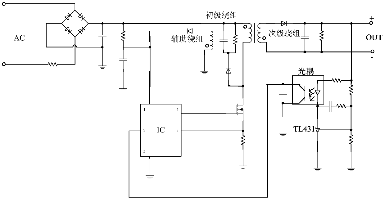
[0004] The circuit diagram of a typical secondary controlled charger scheme is shown in figure 2 As shown, the secondary part adopts optocoupler and TL431, which can detect the change of charging voltage in real time and feed back to the primary control chip IC immediately, and is not affected by the operating frequency of the charger system, so the dynamic response effect of the system is better than that of the charger controlled by the primary The scheme is much better, but the secondary control charger scheme has more components than the primary control, the cost is high, and the loss of the optocoupler and TL431 itself is large, which is not conducive to the application of low-load and no-load power consumption chargers
[0005] The disadvantage of the existing technology is that when the primary control charger solution is used, the dynamic response effect of the system is determined by the minimum operating frequency of the system itself, but with the continuous updating of energy efficiency standards, the standby power consumption of the charger is becoming more and more serious. Harsh, many current charger solutions give up the system dynamic response effect to meet energy efficiency standards, that is to say, in the primary control charger solution, the dynamic response of the system is opposite to the standby power consumption, and it is impossible to meet both of them at the same time. Parameters; when using the secondary control charger solution, the secondary part has many components and high cost, and the optocoupler and TL431 themselves have a large operating loss, which is not conducive to the application of low-load and no-load power consumption chargers. In addition, the primary control chip IC cannot compensate for output line drop

Method used


Image

  • Charging system based on secondary control and secondary control device thereof
  • Charging system based on secondary control and secondary control device thereof
  • Charging system based on secondary control and secondary control device thereof

Examples


Embodiment Construction

[0024] Embodiments of the present invention are described in detail below, examples of which are shown in the drawings, wherein the same or similar reference numerals designate the same or similar elements or elements having the same or similar functions throughout. The embodiments described below by referring to the figures are exemplary only for explaining the present invention and should not be construed as limiting the present invention.

[0025] The following disclosure provides many different embodiments or examples for implementing different structures of the present invention. To simplify the disclosure of the present invention, components and arrangements of specific examples are described below. Of course, they are only examples and are not intended to limit the invention. Furthermore, the present invention may repeat reference numerals and / or letters in different instances. This repetition is for the purpose of simplicity and clarity and does not in itself indicat...


PUM


Abstract

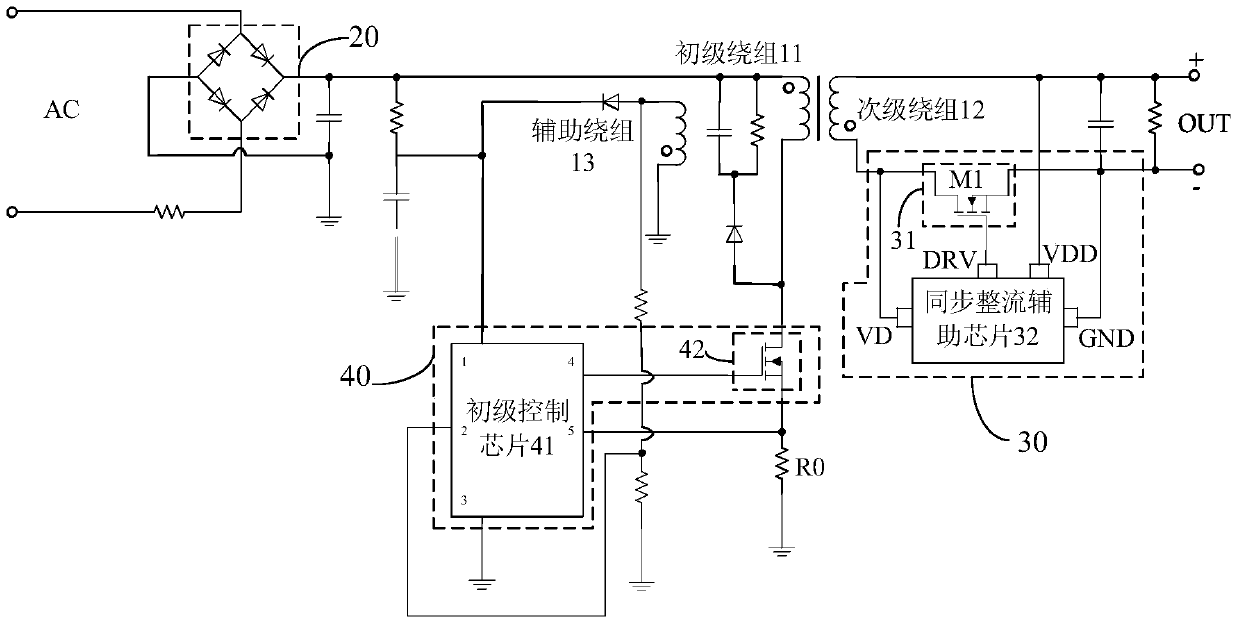
The invention discloses a charging system based on secondary control, which comprises a transformer, a rectifier device, a secondary rectifier switch transistor, a secondary synchronous rectifier auxiliary chip, a primary control chip and a primary switch transistor, wherein the secondary synchronous rectifier auxiliary chip controls opening and closing of the secondary rectifier switch transistor, detects output voltage and controls the secondary rectifier switch transistor to be opened when the output voltage drops and is smaller than a first reference voltage to enable an abrupt voltage to be generated at two ends of a secondary winding, and the abrupt voltage is fed back to an auxiliary winding; the primary control chip controls the primary switch transistor to be opened according to the abrupt voltage to enable the primary winding to be charged and controls the primary switch transistor to be closed when the voltage detected by a voltage detection end is larger than a second reference voltage to enable a primary winding to be discharged. The charging system can realize ultralow standby power consumption of the system and can also achieve effects of optimizing a system dynamic response. The invention also discloses a secondary control device for the charging system based on secondary control.

Description

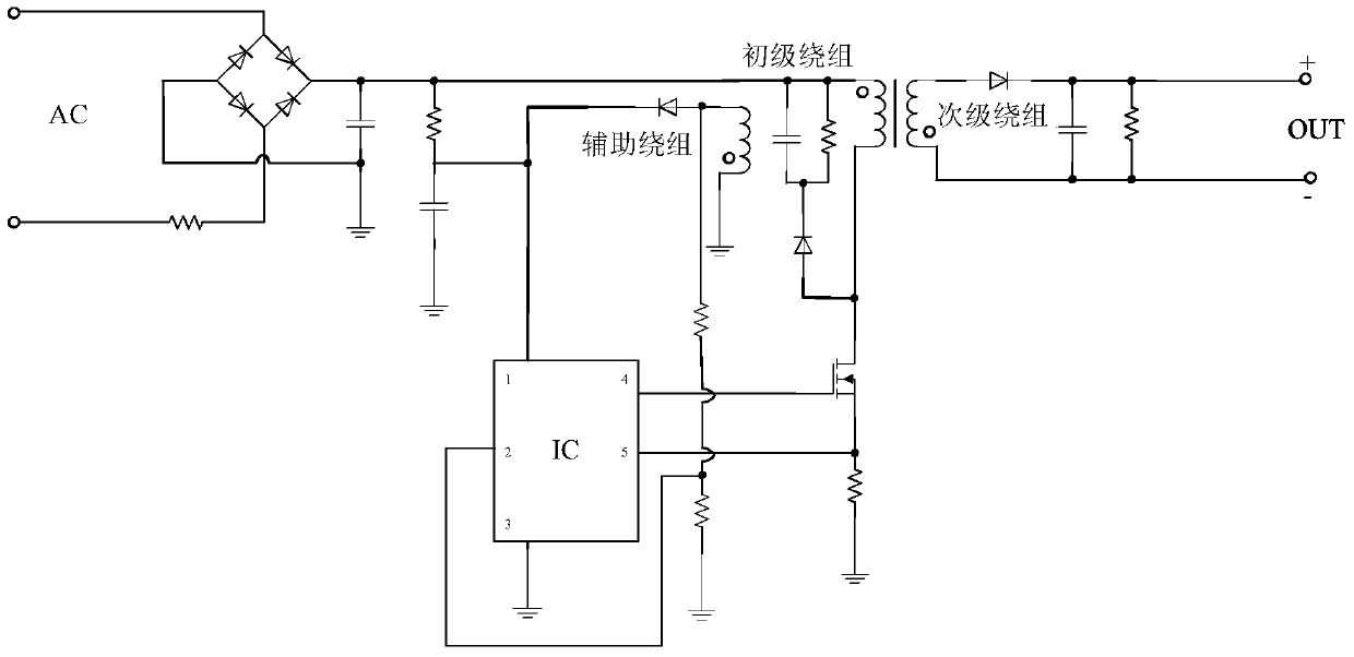
technical field [0001] The invention relates to the technical field of chargers, in particular to a charging system based on secondary control and a secondary control device for the charging system based on secondary control. Background technique [0002] With the unification of the USB interface, most current chargers have certain requirements for the dynamic response of the system. The so-called dynamic response is the fluctuation range of the charger output voltage when the load terminal of the charger switches the load. The current mainstream optimization system dynamic response scheme can be divided into a primary-controlled charger scheme and a secondary-controlled charger scheme. [0003] Among them, the circuit diagram of a typical primary-controlled charger solution is as follows figure 1 As shown, since the output parameters of the charger are in the secondary part, and the primary control chip IC receives the secondary feedback signal only once per switching cycl...

Claims


Application Information

Patent Timeline
IPC IPC(8): H02J7/02
Inventor 叶文辉王文情
Owner BYD SEMICON CO LTD
Learn More