Eureka AIR delivers breakthrough ideas for toughest innovation challenges, trusted by R&D personnel around the world.

A method for supplementing ballistics in the blind area of ​​spacecraft measurement

A spacecraft and blind area technology, applied in the direction of instrumentation, geometric CAD, calculation, etc., can solve the problems of signal instability, long navigation area, and no data of velocity time trajectory, etc., to achieve improved display effect, low coupling, and clear logic Effect

Inactive Publication Date: 2019-02-05
中国人民解放军63791部队
View PDF5 Cites 0 Cited by
  • Summary
  • Abstract
  • Description
  • Claims
  • Application Information

AI Technical Summary

Problems solved by technology

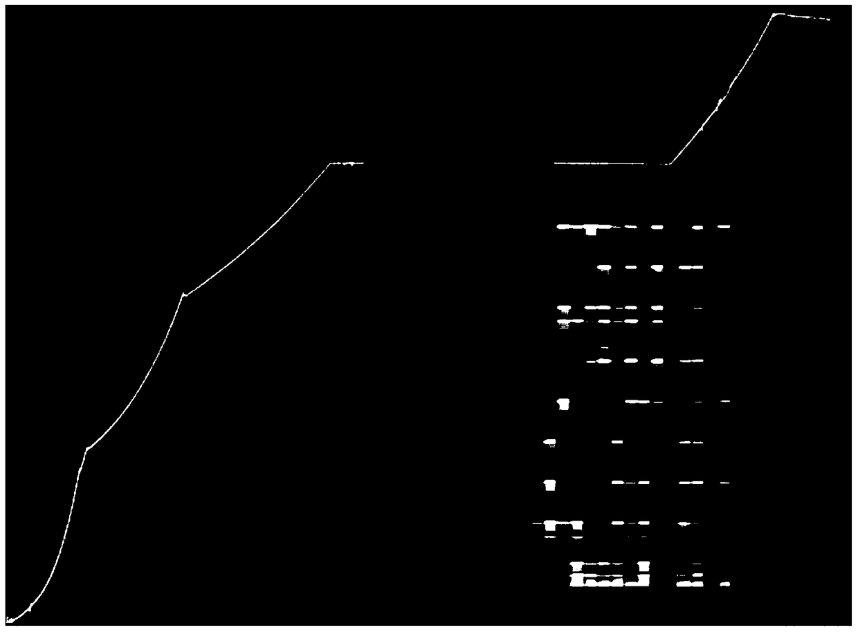
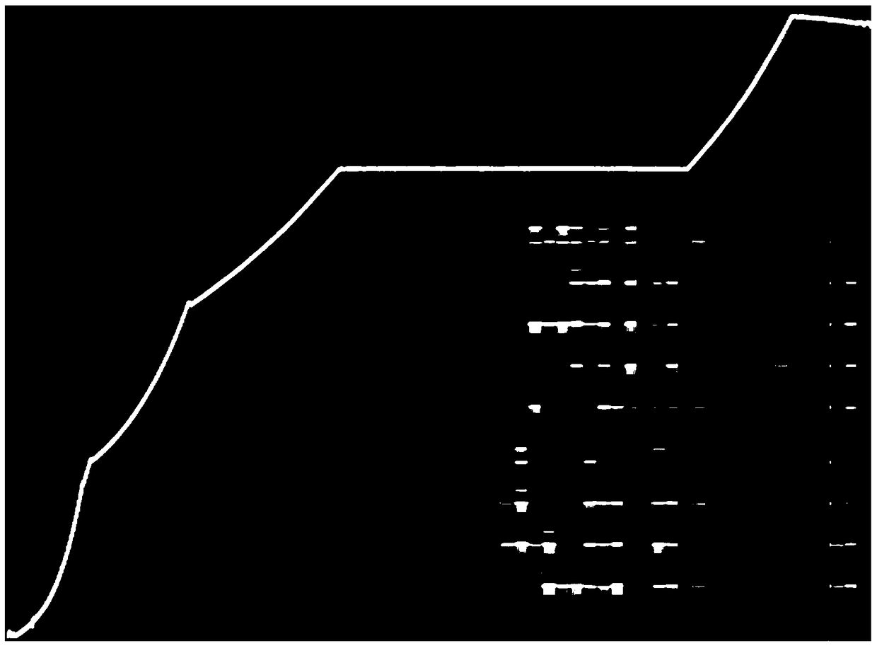
[0002] In the launch mission of the spacecraft, due to the long navigation area, it is difficult to realize uninterrupted tracking, resulting in no data for display in the measurement of the velocity time trajectory in the blind area. Stability, may cause data sometimes not available
The result is that the data breaks in the middle, and the data shows irregular discontinuities near the break point, which greatly affects the display effect and aesthetics

Method used


Image

  • A method for supplementing ballistics in the blind area of ​​spacecraft measurement
  • A method for supplementing ballistics in the blind area of ​​spacecraft measurement
  • A method for supplementing ballistics in the blind area of ​​spacecraft measurement

Examples


Embodiment Construction

[0034] 1. State decomposition

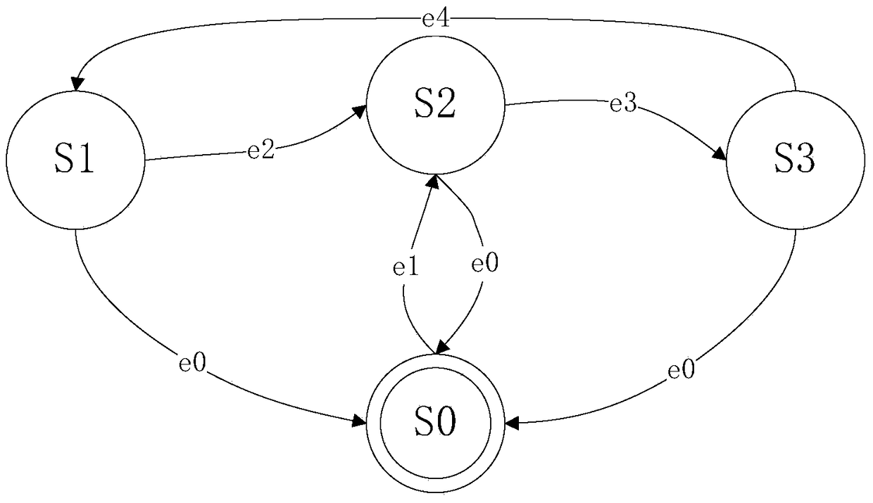
[0035] According to the method of the present invention, the process of supplementing the trajectory is decomposed into 4 states. Form the state change table shown in Table 1. The transition condition indicates that the current state will automatically transfer to the next state after the transition condition is satisfied, and the current state will remain if it is not satisfied.

[0036]

[0037]

[0038] After the states are defined, the input stimuli are processed in their respective states and jump to the next state after the transition conditions are met. A closed loop is formed between states, and it is automatically executed under the management of the state machine. The state transition relationship is as follows: Figure 4 As shown, there are data processing results output in each state.

[0039] 2. Data accumulation in taxiing section

[0040] 1) Define the data structure and related variables

[0041]

[0042] 2) Save the...


PUM


Abstract

The invention discloses a spacecraft measuring blind area trajectory compensating method which comprises the steps of performing fast dynamic control between a trajectory with measuring data and a trajectory without measuring data by using a finite-state machine, and calculating the speed of a measuring blind area trajectory according to the trajectory finally measured before the blind area. By the method, a whole overall trajectory is smoothly continuous, and the displaying effect of the trajectory is remarkably improved. The trajectory compensating method disclosed by the invention is distinct in logic, low in coupling, and in favor of optionally adding boundary conditions latterly according to user requirements.

Description

technical field [0001] The invention relates to a processing method of spaceflight measurement and control velocity time trajectory, which utilizes fast dynamic control of finite state machine between trajectory with measurement data and without measurement data, and calculates trajectory in measurement blind zone according to last measured trajectory before the blind zone. Through this method, the entire ballistic trajectory is smooth and continuous, and the trajectory display effect is significantly improved. Background technique [0002] In the launch mission of the spacecraft, due to the long navigation area, it is difficult to realize uninterrupted tracking, resulting in no data for display in the measurement of the velocity time trajectory in the blind area. Stability may cause data to disappear sometimes. The result is that the data breaks in the middle, and the data shows irregular discontinuities near the break point, which greatly affects the display effect and ae...

Claims


Application Information

Patent Timeline
Patent Type & Authority Patents(China)
IPC IPC(8): G06F17/50
CPCG06F30/15G06F30/23G06F30/367
Inventor 彭渔露何孝港陈锦平刘剑锋王百彦王晟崔健李超杨晓波罗启富
Owner 中国人民解放军63791部队
Why Eureka
Eureka Blog
Learn More