
Touch display panel, driving method thereof and detecting method of induction signals

A touch display panel and sensing signal technology, which is applied in the detection of sensing signals, touch display panel and its driving field, can solve the problems of affecting the report rate, the decline of the conductive performance of thin film transistors, and the long scanning period, etc., and achieve improvement The effect of reporting rate, avoiding leakage phenomenon, and shortening scanning time

Active Publication Date: 2016-04-27
BOE TECH GRP CO LTD +1
View PDF5 Cites 30 Cited by
  • Summary
  • Abstract
  • Description
  • Claims
  • Application Information

AI Technical Summary

Problems solved by technology

[0004] The purpose of the present invention is to provide a touch display panel, its driving method, and the detection method of the sensing signal, which are used to solve the problem of long scanning period of the touch screen under the premise of meeting the requirements of narrow borders and high bonding yield. In turn, the problem of affecting the report rate, and the thin film transistor in the visible area of ​​the touch screen will be affected by the light-induced degradation effect and prone to the problem of reduced conductivity

Method used


Image

  • Touch display panel, driving method thereof and detecting method of induction signals
  • Touch display panel, driving method thereof and detecting method of induction signals
  • Touch display panel, driving method thereof and detecting method of induction signals

Examples


Embodiment Construction

[0030] In order to further illustrate the touch display panel provided by the embodiments of the present invention, its driving method, and the detection method of the sensing signal, a detailed description will be given below in conjunction with the accompanying drawings.

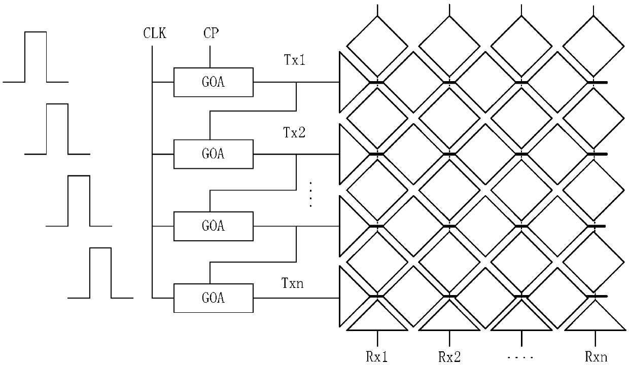
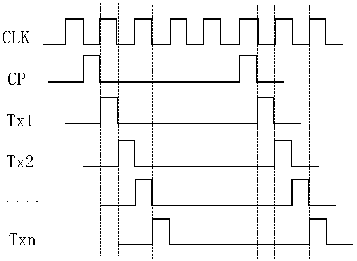
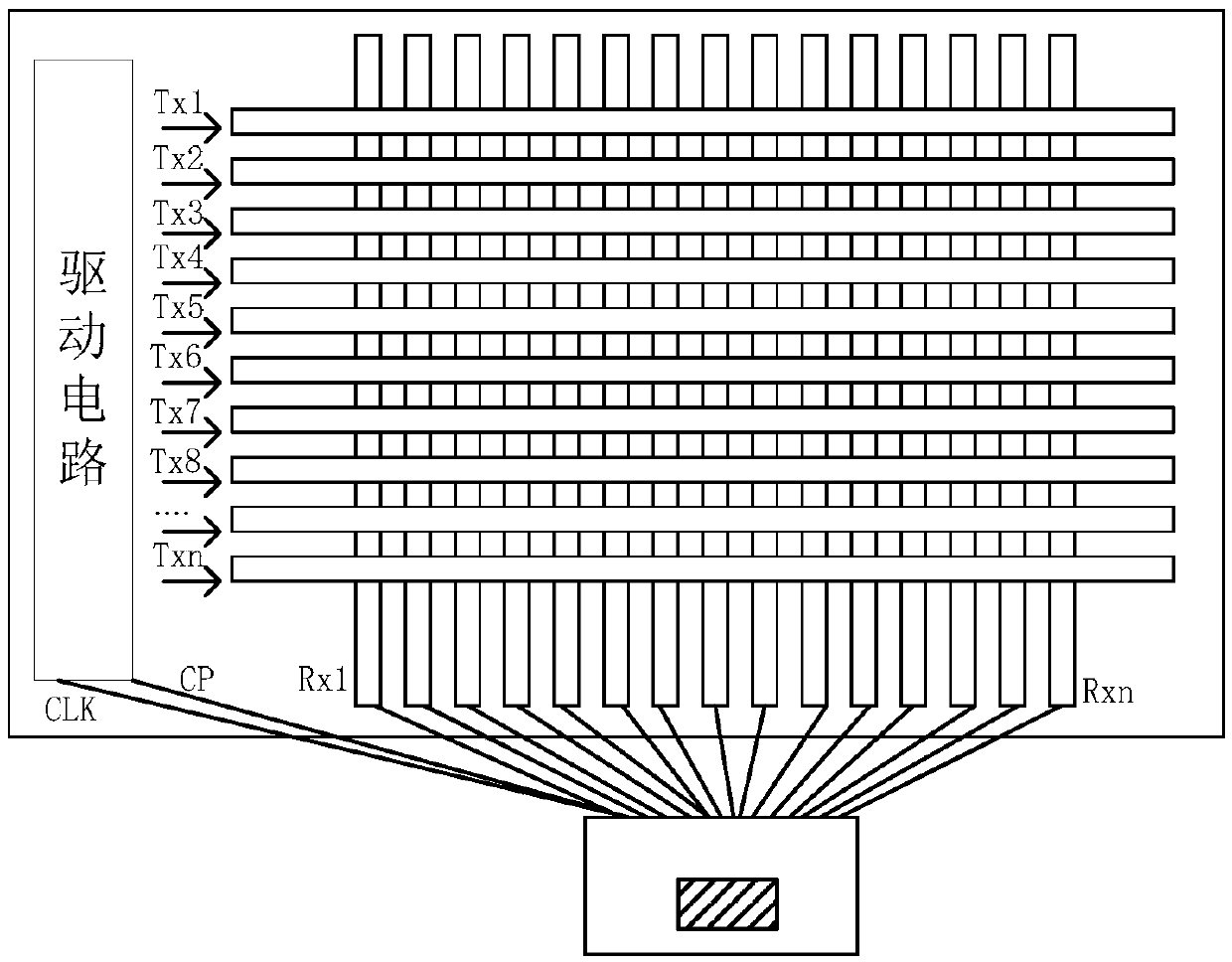
[0031] see figure 1, in the touch display panel provided by the embodiment of the present invention, the touch area of ​​the touch display panel is provided with a plurality of touch driving electrodes and a plurality of touch sensing electrodes, and the edge of the touch display panel is provided for providing the touch display panel with A drive unit for driving signals; wherein, the drive unit includes: the first gate drive circuit to the Nth gate drive circuit sequentially coupled in a cascaded manner, the enabling terminal of the first gate drive circuit is connected to the touch display The field synchronous signal line on the edge of the panel is connected, and the output end of the N-1th gate drive...


PUM


Abstract

The invention discloses a touch display panel, a driving method thereof and a detecting method of induction signals, relates to the field of display and solves the problems that the report rate is influenced due to long scanning period and thin film transistors in a visible range are prone to electrical conductivity reduction. A plurality of touch driving electrodes and touch induction electrodes are arranged in a touch area of the touch display panel, and a driving unit is arranged on the edge; the driving unit comprises a first gate driving circuit to an Nth gate driving circuit which are coupled sequentially in a cascading manner, the enable end of the first gate driving circuit is connected with a field synchronizing signal line arranged on the edge of the touch display panel, and the output end of the (N-1)th gate driving circuit is connected to the enable end of the Nth gate driving circuit adjacently connected with the (N-1)th gate driving circuit; the input ends of the first gate driving circuit to the Nth gate driving circuit are connected with a driving signal line respectively, and the output ends of the first gate driving circuit to the Nth gate driving circuit are coupled with the corresponding touch driving electrodes respectively.

Description

technical field [0001] The present invention relates to the field of display technology, in particular to a touch display panel, a driving method thereof, and a detection method of a sensing signal. Background technique [0002] With the continuous development of display technology, the application of touch screen has become more and more extensive. According to different working principles, touch screens are generally divided into: resistive touch screen, capacitive touch screen and infrared touch screen, etc.; The touch screen generally includes touch driving electrodes and touch sensing electrodes. When the driving signal is input to the touch driving electrodes, the voltage signal coupled by the touch sensing electrodes through the inductive capacitance is correspondingly detected. In this process, when a human body touches the When the capacitive touch screen is used, the electric field of the human body will act on the sensing capacitor, causing the capacitance of the ...

Claims


Application Information

Patent Timeline
Patent Type & Authority Applications(China)
IPC IPC(8): G06F3/041
CPCG06F3/0412G06F2203/04111G06F3/04166G06F3/0443G06F3/0445G06F3/0446G06F2203/04102G06F2203/04103
Inventor 杨清邵贤杰冯思林
Owner BOE TECH GRP CO LTD
Learn More