Drive-amount changing mechanism for crank driving apparatus

A technology of driving device and changing mechanism, applied in the direction of transmission device, loom, mechanical equipment, etc., can solve the problems of accurate and consistent eccentricity, adverse weaving effect, operator burden, etc.

Active Publication Date: 2016-04-27
TSUDAKOMA KOGYO KK
View PDF7 Cites 1 Cited by
  • Summary
  • Abstract
  • Description
  • Claims
  • Application Information

AI Technical Summary

Problems solved by technology

In this case, the operation can be performed relatively easily as long as the other supporting member is in contact with the locking portion, but in the operation of the intermediate position where the other supporting member is not in contact with the locking portion, the The operator has to support all of the above weights, so this operation places a great burden on the operator
[0014] In addition, in the case of the structure in which the above-mentioned easing device is installed on both sides of the tension roller (both sides are driven), when changing the eccentricity, it is necessary to change the same amount on both sides. At the same time, in the structure where the operator has to perform positioning at the middle position, if the eccentricity of the position of the bracket relative to the crank hub is to be exactly the same on both sides, it is extremely difficult for one operator to perform the operation, and multiple operators are required. to perform the operation
In addition, even in the case of multiple operators, it is difficult to precisely match the eccentricity on both sides, which may result in different drive amounts (looseness) on both sides of the tension roller, which may cause problems for weaving. bring adverse effects

Method used


Image

  • Drive-amount changing mechanism for crank driving apparatus
  • Drive-amount changing mechanism for crank driving apparatus
  • Drive-amount changing mechanism for crank driving apparatus

Examples


Embodiment Construction

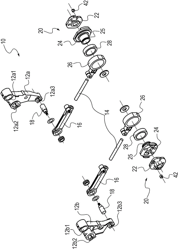
[0036] Hereinafter, embodiments of the present invention will be described in detail based on the drawings. Figure 1 to Figure 6 One embodiment of the present invention is shown, that is, a case where the crank type driving device provided with the driving amount changing mechanism according to the present invention is applied to an easing device of a loom.

[0037] figure 1 The outline of the easing device of the loom to which the present invention is applicable is shown, that is, the easing device 10 includes a pair of easing rods 12a for supporting a tension roller (not shown) around which a warp yarn is wound. .

[0038] Each of the easing bars 12a, 12b is rotatably supported on the loom frame via support shafts (not shown) inserted in support holes 12a1, 12bl formed at the upper ends of the respective easing bars 12a, 12b. Moreover, the shaft parts of both ends of a tension roller are fitted and fixed to the support hole 12a2, 12b2 formed in the intermediate part of ea...


PUM


Abstract

The utility model provides a drive quantitative change among crank formula drive arrangement is mechanism more should drive the more characterized in that of mechanism of quantitative change, dispose in the supporting part of the party of first support component and second support component including fixed, and support in this supporting part and the position control part that sets up with the another party's with first support component and second support component the mode at the face butt that extends in the criss -cross direction with eccentricity direction, through making the position control part rotate for the supporting part, the change is from the supporting part to the position control part for the distance of the butt position of another party's support component, and change first support component and the relative position of second support component on eccentricity direction. Can carry out second support component (bracket) easily for the regulation of the offset of first support component (crank boss) and at intermediate position second support component for the drive quantitative change of the location of first support component more in this crank formula drive arrangement.

Description

technical field [0001] The invention relates to a driving amount changing mechanism in a crank type driving device. Background technique [0002] As a known crank type driving device, there is one disclosed in Patent Document 1 below. The crank drive device in this patent document 1 (hereinafter referred to as "conventional device") includes a first support member non-rotatably assembled with respect to the drive shaft, a second support member non-rotatably assembled with respect to the first support member A member, an eccentric shaft supported by the second support member, and a connecting member rotatably supported by the second support member via the eccentric shaft and connected to the member to be driven. Moreover, according to the existing device, by assembling the second support member on the first support member in such a manner that the axis center of the eccentric shaft is eccentric with respect to the axis center of the drive shaft, as the first and second suppo...

Claims


Application Information

Patent Timeline
Patent Type & Authority Applications(China)
IPC IPC(8): F16H21/20
CPCD03D49/22F16H21/20F16H21/22
Inventor 山岸大吾
Owner TSUDAKOMA KOGYO KK
Why Eureka
Try Eureka