Pipe-bending forming mechanism in pipe bending machine

A technology of forming mechanism and pipe bending machine, which is applied in metal processing equipment, feeding device, positioning device, etc., can solve the problems of clamping mold and wheel mold damage, mold clamping too tight or too loose, affecting the quality of bending pipe, etc. Achieve the effect of ensuring molding quality, reducing maintenance costs and improving work efficiency

Inactive Publication Date: 2016-04-27
ZHANGJIAGANG XINGYU MACHINERY MFG
View PDF7 Cites 9 Cited by
  • Summary
  • Abstract
  • Description
  • Claims
  • Application Information

AI Technical Summary

Problems solved by technology

[0004] The bending pipe forming mechanism of the above-mentioned structure has the following disadvantages: 1. The wheel mold cavity and the clamp mold cavity are arranged horizontally opposite to each other in the left and right directions, so that the pipe to be bent cannot be naturally placed in the wheel mold cavity under the action of its own gravity. or the clamping mold cavity, so before the clamping mold and the wheel mold are clamped and closed, the operator needs to hold the pipe to be bent and make the side of the pipe to be bent lean against the wheel mold cavity, so as to ensure that the clamping mold and the wheel mold When the molds are clamped to each other, the pipe to be bent can be clamped in the wheel mold cavity and the clamp mold cavity, which makes the clamping operation of the pipe more cumbersome
In addition, since the operator needs to hold the pipe when clamping the pipe to be bent, it is not suitable to set up multiple pairs of cavities on the clamping mold and the wheel mold, that is, the above-mentioned traditional pipe bending mechanism is inconvenient to bend multiple pipes at the same time Forming, which leads to low production efficiency; 2. The clamping mold is directly connected to the piston rod of the oil cylinder. When the clamping mold and the wheel mold are closed, the piston rod needs to bear a large force, which is easy to cause in the actual use process. Damaged piston rod
In addition, the moving distance of the clamping mold is completely determined by the telescopic distance of the piston rod of the oil cylinder. When it is necessary to process some pipes with larger diameters, the length of the piston rod can only be lengthened, but this also makes the piston rod easier to damage. Increased maintenance costs; 3. During the use of the oil in the oil cylinder, the temperature of the oil will inevitably rise and the volume of the oil will expand. In the case of cold weather in winter, the temperature of the oil will decrease and cause The shrinkage of the oil volume will lead to errors in the moving distance of the clamping mold when closing the mold, and it is easy to cause the clamping mold to be too tight or too loose. If the clamping mold is too tight, it will cause damage to the clamping mold and the wheel mold. If it is too loose, the pipe cannot be clamped, which will affect the quality of the bend

Method used


Image

  • Pipe-bending forming mechanism in pipe bending machine
  • Pipe-bending forming mechanism in pipe bending machine
  • Pipe-bending forming mechanism in pipe bending machine

Examples


Embodiment Construction

[0021] The technical solutions of the present invention will be further described in detail below in conjunction with the accompanying drawings and preferred embodiments.

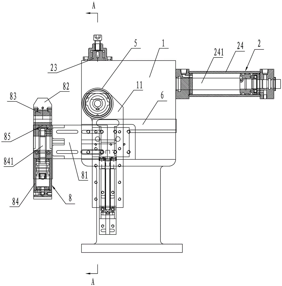
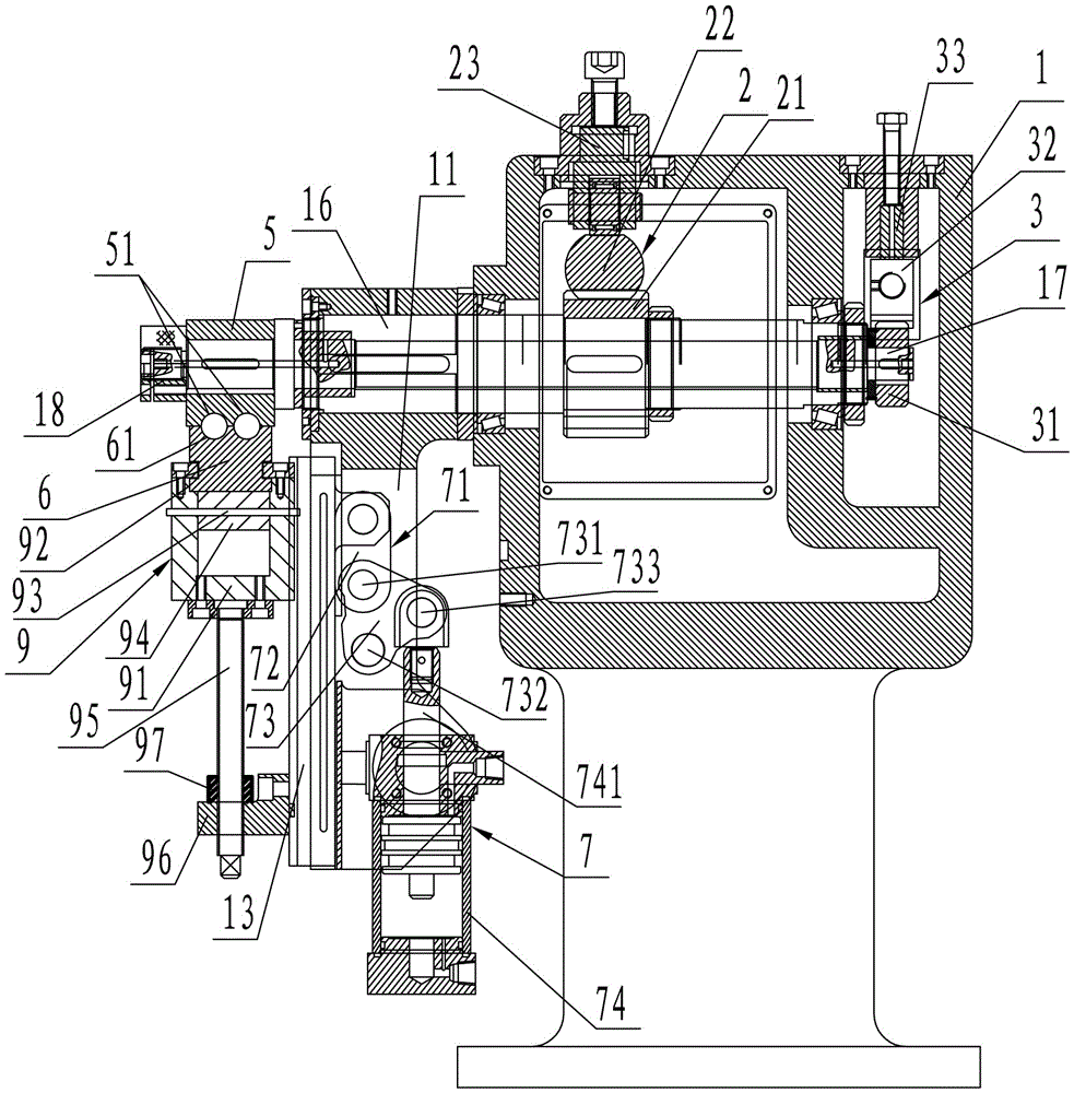
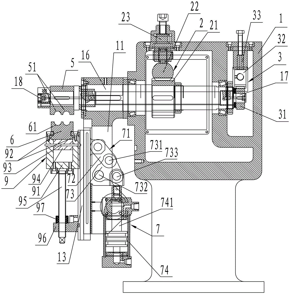
[0022] Such as figure 1 , figure 2 , image 3As shown, the pipe bending forming mechanism in the pipe bending machine includes: a casing 1, a main shaft 16 is movably supported in the casing 1, and the main shaft 16 is arranged in a horizontal direction. Installed on the casing 1, the front end of the main shaft 16 is provided with an elbow arm 11. Under the action of the main driving mechanism 2, the main shaft 16 can rotate around its own central axis so as to drive the elbow arm 11 to rotate synchronously. In this embodiment, the main driving mechanism 2 includes a large gear 21 fixedly sleeved on the main shaft 16, and a matching curved pipe rack 22 is provided on the large gear 21, and the back of the curved pipe rack 22 is installed Pressed by the large rack press seat 23 in the casing 1, the larg...


PUM


Abstract

The invention discloses a pipe-bending forming mechanism in a pipe bending machine and belongs to the field of pipe bending machines. The pipe-bending forming mechanism in the pipe bending machine comprises a machine shell. A main shaft is movably supported in the machine shell and arranged in the horizontal direction. A main driving mechanism is arranged on the main shaft. A pipe bending arm is arranged at the front end of the main shaft. A die rotating shaft is movably arranged in the main shaft. Both the front end and the rear end of the die rotating shaft stretch out of the main shaft. A bending die is arranged at the front end of the die rotating shaft. A clamping die is arranged below the bending die. A die stripping driving mechanism is arranged at the rear end of the die rotating shaft. A die assembly driving mechanism and a sliding rail are arranged on the pipe bending arm. A sliding block is arranged in the sliding rail. The two sides of the sliding block are connected with the die assembly driving mechanism and a die assembly adjustment component respectively, and the die assembly adjustment component is used for adjusting the distance between the clamping die and the bending die. The die assembly adjustment component is connected with the clamping die. The clamping die and the bending die can be driven by the die assembly driving mechanism to be assembled or separated. The pipe-bending forming mechanism in the pipe bending machine has the advantages that a pipe to be bent does not need to be held manually when clamped, displacement distance errors, generated when the volume of hydraulic oil changes, of the clamping die can be eliminated, and the maintenance cost can be reduced.

Description

technical field [0001] The invention relates to the field of pipe bending machines, in particular to a pipe bending forming mechanism in the pipe bending machine. Background technique [0002] The pipe bending machine is a processing equipment for bending and forming pipes. At present, a pipe bending mechanism commonly used in pipe bending machines includes: a workbench, a spindle is movable supported in the workbench, the spindle is set in the vertical direction, and the upper end of the spindle is provided with a bend. The pipe arm and the main shaft outer fixed sleeve are provided with a main transmission gear, and the main transmission gear is meshed with a main driving gear, and the main driving gear is installed on the output rotating shaft of the main motor. Driven by the main motor, the main shaft can rotate and drive the pipe bending arm to rotate. A rotary mold shaft is arranged inside the main shaft, the upper and lower ends of the rotary mold shaft protrude from...

Claims


Application Information

Patent Timeline
Patent Type & Authority Applications(China)
IPC IPC(8): B21D7/16B21D43/00
CPCB21D7/16B21D43/003
Inventor 杨孙涛李萍孙国兴孙萍萍
Owner ZHANGJIAGANG XINGYU MACHINERY MFG
Why Eureka
Try Eureka