Power conversion circuit, power conversion method and air conditioner

A technology for power conversion and switching circuits, which is applied in output power conversion devices, conversion of AC power input to DC power output, electrical components, etc. Low heat, reduced heat generation, and small device size

Inactive Publication Date: 2016-04-20
WUHAN REFRIGERATION EQUIP OF MIDEA GROUP
View PDF5 Cites 8 Cited by
  • Summary
  • Abstract
  • Description
  • Claims
  • Application Information

AI Technical Summary

Problems solved by technology

However, when working, at least three power devices in the main circuit have current flowing through them, so there are problems of high heat generation and large loss during high-power applications. In addition, all currents flow through one IGBT, which also restricts high-power applications.

Method used


Image

  • Power conversion circuit, power conversion method and air conditioner
  • Power conversion circuit, power conversion method and air conditioner
  • Power conversion circuit, power conversion method and air conditioner

Examples


Embodiment 1

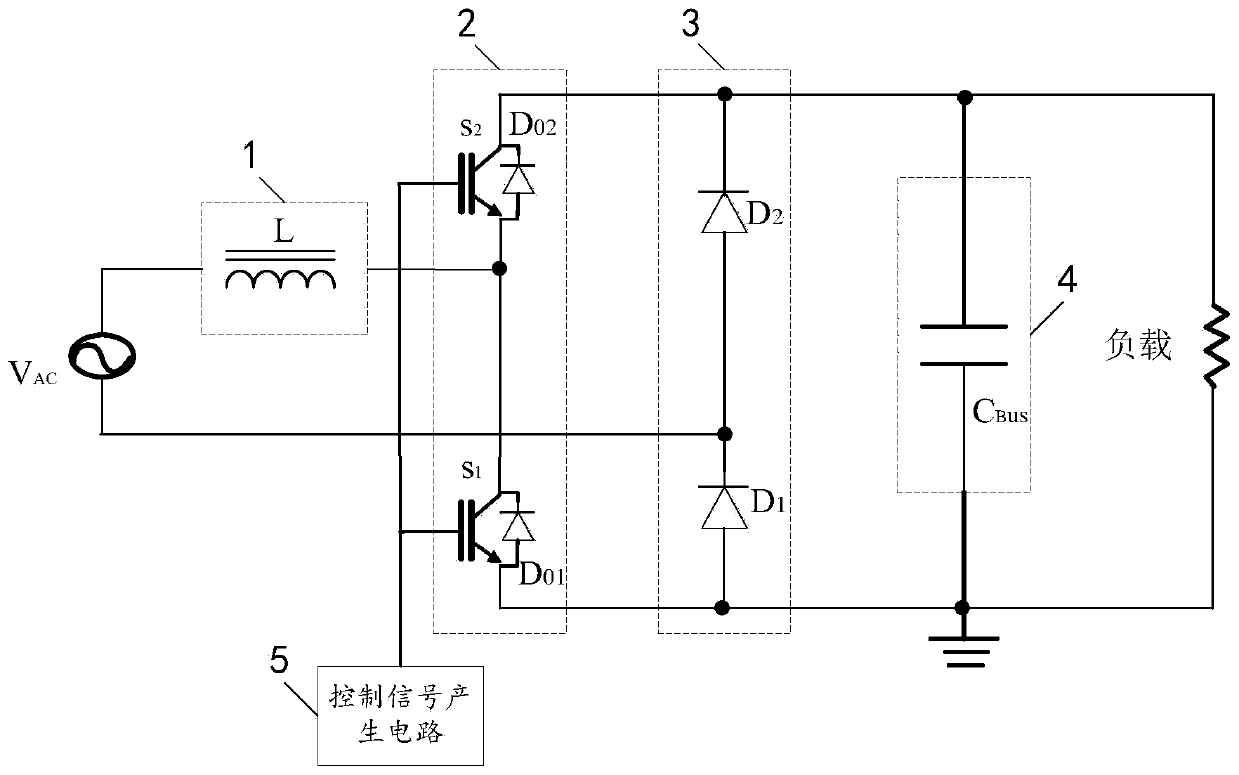
[0020] Example 1, such as figure 1 As shown, a power conversion circuit includes a first energy storage circuit 1, a half-bridge switching circuit 2, a rectifier circuit 3, a second energy storage circuit 4 and a control signal generation circuit 5; one end of the AC power supply is connected to the first energy storage circuit 1 One end of the first energy storage circuit 2 is connected to the half-bridge switching circuit 3, the half-bridge switching circuit 4, the rectifier circuit 4, the second energy storage circuit 5 and the load are connected in parallel; the other end of the AC power supply is connected to the rectifier circuit 3, and the control The signal generating circuit 5 is connected to the half-bridge switching circuit 2, and controls the two switching tubes in the half-bridge switching circuit to work in a complementary manner during the entire AC cycle, and only controls one switching tube to be on and off in each half of the AC cycle, and the other switching ...

Embodiment 2

[0023] Embodiment 2, the difference from Embodiment 1 is that both the first switch tube S1 and the second switch tube S2 use IGBTs, and the gates of the first switch tube S1 and the second switch tube S2 are connected to the control signal generating Circuit, the collector of the first switching tube S1 and the emitter of the second switching tube S2 are connected to one end of the AC power supply through the first energy storage circuit; the emitter of the first switching tube S1 is connected to the first diode D1 The anode, the cathode of the first diode D1 and the anode of the second diode D2 are all connected to the other end of the power supply, and the cathode of the second diode D2 is connected to the collector of the second switching transistor S2.


PUM


Abstract

The invention relates to a power conversion circuit, a power conversion method and an air conditioner. The power conversion circuit comprises a first energy storage circuit, a half-bridge switching circuit, a rectification circuit, a second energy storage circuit and a control signal generating circuit. One end of an AC power supply is connected with one end of the first energy storage circuit, and the other end of the first energy storage circuit is connected with a half-bridge switching circuit. The half-bridge switching circuit, the rectification circuit, the second energy storage circuit and a load are connected in parallel. The other end of the AC power supply is connected with the rectification circuit. The control signal generating circuit is connected with the half-bridge switching circuit. The power conversion circuit according to the invention has advantages of small number of elements, simple circuit structure, small size of a device in which the power conversion circuit is mounted, and low cost. In the positive half period and the negative half period of power supply input voltage, the current just flows over two power devices, thereby effectively reducing the number of power elements in a current path, effectively reducing heating amount and improving conversion efficiency. Furthermore the power conversion circuit has advantages of low common-mode interference, and easy EMI realization.

Description

technical field [0001] The invention relates to the technical field of power conversion, in particular to a power conversion circuit, method and air conditioner. Background technique [0002] In the prior art, some loads are impure resistive loads. For example, the load of an inverter air conditioner is a compressor motor, and the compressor motor is an impure resistive load. There is a situation where the voltage and current phases are inconsistent, and the current of the traditional inverter circuit is rectified and filtered. The waveform is distorted, the power factor is low and the harmonics are large, causing serious pollution to the power grid. Therefore, a power conversion circuit (hereinafter referred to as PFC) must be introduced to make the input current harmonics meet the existing harmonic requirements. [0003] The traditional BOOST PFC is widely used because of its simple structure and good stability. However, when working, at least three power devices in the m...

Claims


Application Information

Patent Timeline
Patent Type & Authority Applications(China)
IPC IPC(8): H02M7/219H02M1/32
CPCH02M7/219H02M1/32
Inventor 苏立志李洪涛阳序仁
Owner WUHAN REFRIGERATION EQUIP OF MIDEA GROUP
Why Eureka
Try Eureka