


Quick Research
Generate reliable direction feasibility study reports for your R&D in just a few steps.

Technical Q&A
Discover and master advanced knowledge NOW. Basics, ideas, possibilities, all at once.

Find Solutions
As an expert in R&D theories, this can generate solutions to your technical problems instantly.

Evaluate Feasibility
Analyze your overall solution with one click, know your potential R&D risks in advance.

Monitor Landscape
Get weekly tech updates, stay abreast of the latest tech innovations and key insights.
A device for cleaning the inner wall of an oval pipe
An oval-shaped, pipeline technology, applied in the field of pipeline cleaning equipment, can solve the problems of human body damage, heavy cleaning, low cleaning efficiency, etc., to avoid human injury, high cleaning efficiency, and solve the effect of cleaning dead corners
- Summary
- Abstract
- Description
- Claims
- Application Information
AI Technical Summary
Problems solved by technology
Method used
Image

Examples
Embodiment 1
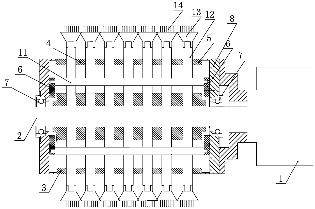
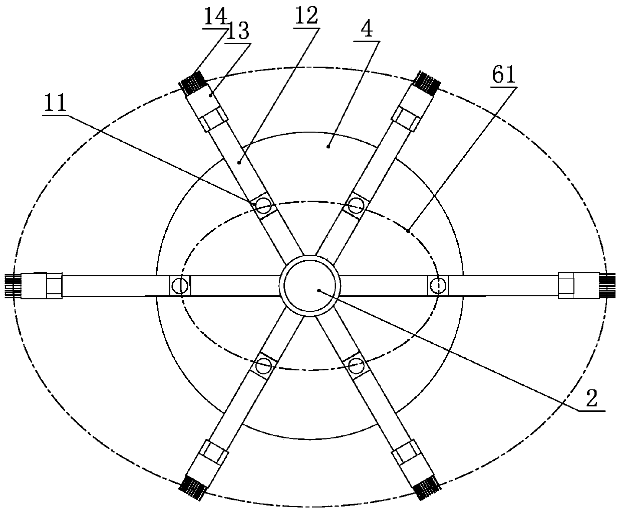
[0036] Embodiment 1: The central rotating shaft 2 is connected to the output end of the motor 1, and the central rotating shaft 2 is a power transmission part, which transmits the power of the motor 1 to the cleaning part. The two ends of the central rotating shaft 2 are connected with the end casing 8 through the bearing 7 to realize the fixing of the central rotating shaft 2 and the end casing 8, and a bearing end cover is arranged on the outside of the bearing. An elliptical guide wheel 6 is respectively sleeved inside the bearings at the left and right ends of the central shaft 2. The guide wheel is in the shape of a round cake. The center of the guide wheel is provided with a central hole that matches the central shaft. Hole 62, the guide wheel and the end casing are fixed by screws. The inner side of the guide wheel is provided with an elliptic guide chute 61 along the periphery of the guide wheel, and the two guide wheels are provided with opposite sides of the guide ch...
Embodiment 2
[0045] Embodiment 2: Further, on the right sides of the left runner and the middle runner, there are uniformly provided with a plurality of slots 10 for fixing the intermediate connector corresponding to the positions of the slots, that is, each slot position corresponds to There is a radial card slot corresponding to the intermediate connector of the cleaning part, the intermediate connector and the card slot are clearance fit, that is, when the insertion rod moves in the through groove, the intermediate connector moves in the card slot , The intermediate connecting piece is limited by the card slot, so there will be no shaking during the cleaning process, ensuring the strength of the cleaning parts. The draw-in slots are evenly and symmetrically distributed, and the number of draw-in slots and through slots is preferably an even number to ensure uniform force and stable operation of the cleaning parts for moving and cleaning.
Embodiment 3
[0046] Embodiment 3: Further, on the left sides of the middle runner and the right runner, corresponding to the positions of the through grooves, there are evenly provided a number of slots for fixing the intermediate connectors, and the slots are evenly and symmetrically distributed . Its installation and design method is the same as that of Embodiment 2, and its technical effect is also the same, so it will not be repeated here.
[0047] Further, the right side of the left runner and the left side of the middle runner, the right side of the middle runner and the left side of the adjacent middle runner, the right side of the middle runner and the left side of the right runner There is a gap between the sides to prevent the interference of the rotors during the cleaning process.
[0048] The upper surface of the insertion rod is provided with a threaded hole, and the bottom of the intermediate connector is provided with an external thread matched with the threaded hole. Duri...
PUM
 Abstract
Description
Claims
Application Information
 - R&D Engineer
- R&D Manager
- IP Professional
- Industry Leading Data Capabilities
- Powerful AI technology
- Patent DNA Extraction
Browse by: Latest US Patents, China's latest patents, Technical Efficacy Thesaurus, Application Domain, Technology Topic, Popular Technical Reports.
© 2024 PatSnap. All rights reserved.Legal|Privacy policy|Modern Slavery Act Transparency Statement|Sitemap|About US| Contact US: help@patsnap.com