
Spring operating mechanism for circuit breaker

A technology of operating mechanism and circuit breaker, applied in contact drive mechanism, power device inside the switch, etc., can solve the problem of unstable coordination characteristics and mechanical characteristics of the transmission system, low relative position accuracy of installation, and reduced circuit breaker reliability. and other problems, to achieve the effect of compact overall structure of the mechanism, improving energy conversion efficiency, and enhancing stability and reliability

Active Publication Date: 2016-04-20
国电博纳(北京)电力设备有限公司
View PDF6 Cites 8 Cited by
  • Summary
  • Abstract
  • Description
  • Claims
  • Application Information

AI Technical Summary

Problems solved by technology

The modular structure is easy to assemble, but its structure is complex, the shape is large, and the cost is high
The position of the mechanism with scattered parts is accurate, but there are many parts, it is not easy to assemble, and the processing accuracy is high, which brings a relatively high processing cost
The split structure can be installed independently, easy to assemble, and easy to generalize. However, this type of mechanism needs to be debugged after installation with the circuit breaker. In addition, the structure is complex and the relative position accuracy of the installation is not high, which makes the matching characteristics and mechanical characteristics of the transmission system unstable. , reducing the reliability of the circuit breaker

Method used


Image

  • Spring operating mechanism for circuit breaker
  • Spring operating mechanism for circuit breaker
  • Spring operating mechanism for circuit breaker

Examples


Embodiment Construction

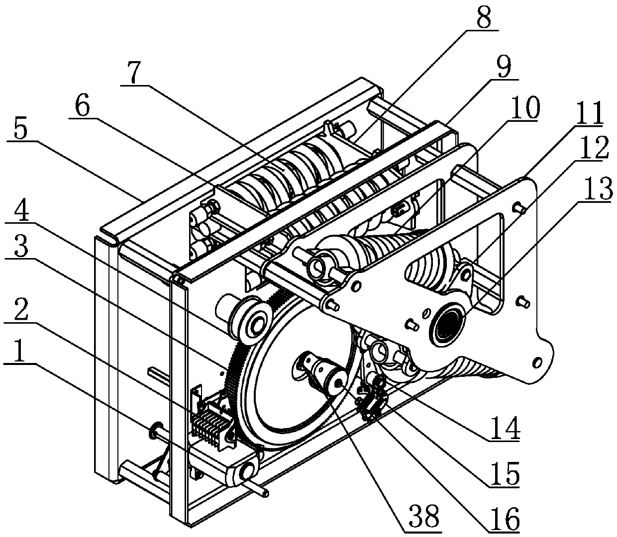
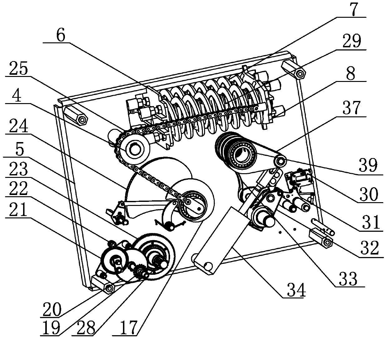
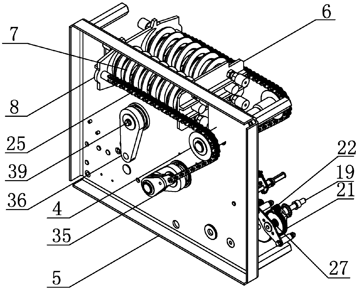
[0020] Such as Figure 1-Figure 4 As shown, the spring operating mechanism for a circuit breaker of the present invention includes two first side plates 9 and a second side plate 5 arranged side by side, the first side plate 9 and the second side plate 5 are integrated with an energy storage system, Closing and closing control systems, opening and closing control systems and auxiliary systems.

[0021] The energy storage system includes an energy storage shaft 16, the energy storage shaft 16 is installed between the first side plate 9 and the second side plate 5, and one end of the energy storage shaft 16 is equipped with a second energy storage arm 35, and the second energy storage arm 35 is installed. The arm 35 is located outside the second side plate 5, the other end of the energy storage shaft 16 is equipped with an energy storage gear 3, the energy storage gear 3 is located outside the first side plate 9, and the end face of the energy storage gear 3 is equipped with a f...


PUM


Abstract

The invention discloses a spring operating mechanism for a circuit breaker, relates to the field of high-voltage switches, and aims to provide a spring operating mechanism for the circuit breaker, which is short in brake separating and closing time, stable and reliable in mechanical property, low in energy loss and small in size. The spring operating mechanism for the circuit breaker provided by the invention comprises a first side plate and a second side plate; an energy storage system, a brake closing and brake closing control system and a brake separating and brake separating control system are integrated on the first side plate and the second side plate. The energy storage system comprises an energy storage shaft, an energy storage gear, an auxiliary cam, a first energy storage crank arm, a second energy storage crank arm, a motor, a chain and an energy storage spring component; the brake separating and brake separating control system comprises an output shaft; an output crank shaft, a special-shaped crank arm, a buffer arm and a central crank shaft are arranged on the output shaft in a penetrating manner in sequence; two brake separating springs are mounted on the central crank shaft; the brake closing and brake closing control system comprises an energy storage latch; the upper end of the energy storage latch and a brake closing limiting bearing are mounted in a matched manner; a brake closing limiting latch is in contact with the energy storage latch.

Description

technical field [0001] The invention relates to the field of high-voltage switches, in particular to a spring operating mechanism that provides a power source for closing and breaking a circuit breaker. Background technique [0002] In the field of high-voltage power transmission and transformation, high-voltage circuit breakers are the last link in the chain of protection devices for power supply systems. Within milliseconds, the operating mechanism must provide the energy required to switch the breaker from a good conductor to a good insulator. A fault in the operating mechanism usually means failure of the breaking operation. Therefore, for the reliability of the circuit breaker and the entire power supply system, the operating mechanism plays a very important role. [0003] At this stage, the operating mechanisms used for high-voltage circuit breakers can be divided into hydraulic operating mechanisms, pneumatic operating mechanisms and spring operating mechanisms. Am...

Claims


Application Information

Patent Timeline
IPC IPC(8): H01H3/32H01H3/30H01H3/26
CPCH01H3/26H01H3/30H01H3/32
Inventor 丛明星王兴达
Owner 国电博纳(北京)电力设备有限公司
Learn More