A method and device for equal delay wiring
A wiring method and isochronous technology, applied in the field of delay wiring method and device, can solve the problems of increasing the volume and area of circuit boards, not involving wiring with equal delay, and being unfavorable for integrated circuit design, etc., so as to increase the main frequency , reduced width and length, and improved integration performance
- Summary
- Abstract
- Description
- Claims
- Application Information
AI Technical Summary
Problems solved by technology
Method used
Image


Examples
Embodiment 1
[0062] figure 1 It is a processing flowchart of the equal-delay wiring method of the present invention. by figure 1 As an example, the equal-delay wiring method of the present invention has the following steps:
[0063] S01: Read in the information of the wiring area and the ports to be wired, including the number and position of the start port and the end port, and the size, position and / or shape of the wiring area.
[0064] S02: Divide the wiring area into series of geometric subsections. After the division, all the network cables subsequently laid in the wiring area are also divided into series of geometric subsections. Number each network cable and its divided geometric sub-segments, and store the calculated resistance and capacitance parameters, network cable width and network cable width adjustment value under the corresponding number.
[0065] S03: Generate the initial wiring in a manner of equal width, that is, the width of each initial network line is the same. Fu...
Embodiment 2
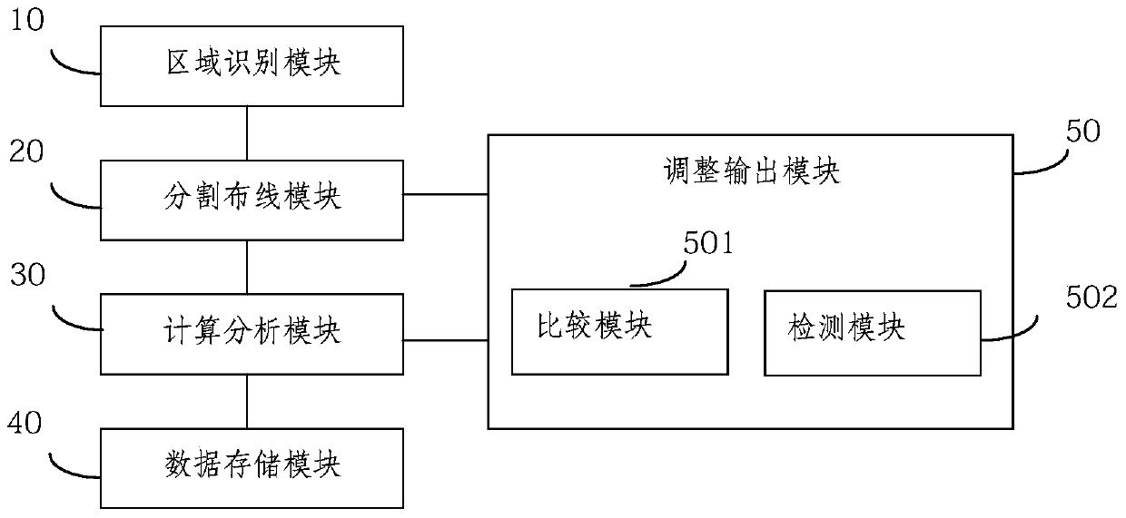
[0073] The present invention also provides an equal-delay wiring device applying the equal-delay wiring method of the present invention, and the delay wiring device can be connected with wiring software. figure 2 Shown is a schematic structural diagram of the equal-delay wiring device of the present invention. Such as figure 2 As shown, the equal delay routing device includes an area identification module 10 , a division routing module 20 , a calculation and analysis module 30 and an adjustment output module 50 .
[0074] An area identification module for identifying geometric parameters of an area to be routed. The geometric parameters may be the shape, size, position and port information of the area to be routed. The port information to be routed is the number and location of initial and / or final ports. The user can select the size of the area to be routed by mouse, touch, and slide, and read the information of the start port and the end port by selecting or clicking wi...
Embodiment 3
[0083] The method for dividing the area to be wired, the calculation method for the resistance and capacitance of the geometric subsection, the calculation method for the time delay of the network cable and the calculation method for the network cable width adjustment value involved in the present invention will be described in detail below in conjunction with the accompanying drawings.
[0084] The division method of the area to be routed:
[0085] image 3 It is a schematic diagram of division of the area to be wired according to the present invention. Such as image 3 As shown, the area surrounded by the solid line in the figure is the area to be routed. From image 3 It can be seen from the figure that after division, the area to be routed is divided into three series of irregular convex quadrilaterals.
[0086] Figure 4 It is another schematic diagram of division of the area to be wired according to the present invention. Such as Figure 4 As shown, after the divi...
PUM
 Abstract
Description
Claims
Application Information
 - R&D
- Intellectual Property
- Life Sciences
- Materials
- Tech Scout
- Unparalleled Data Quality
- Higher Quality Content
- 60% Fewer Hallucinations
Browse by: Latest US Patents, China's latest patents, Technical Efficacy Thesaurus, Application Domain, Technology Topic, Popular Technical Reports.
© 2025 PatSnap. All rights reserved.Legal|Privacy policy|Modern Slavery Act Transparency Statement|Sitemap|About US| Contact US: help@patsnap.com