Universal milling force modeling method for uniform plough model
A modeling method and milling force technology, applied in the direction of electrical program control, digital control, etc., can solve problems such as poor versatility
- Summary
- Abstract
- Description
- Claims
- Application Information
AI Technical Summary
Problems solved by technology
Method used
Image
Examples
Embodiment 1
[0055] (1) The calibration test adopts 7 groups of down milling experiments, the selected radius R is 8mm, the helix angle β is 32°, and the normal rake angle α n 15°, number of teeth N f A carbide end mill with a value of 3 performs down milling on an aluminum alloy 7050-T7451 in a three-coordinate vertical machining center. Calibration test parameters are tool spindle speed 1000RPM, single tooth feed f is 0.03, 0.05, 0.08, 0.10, 0.12, 0.15, 0.18mm / tooth, axial depth of cut a p Equal to 2mm, radial depth of cut a e Equal to 8mm.
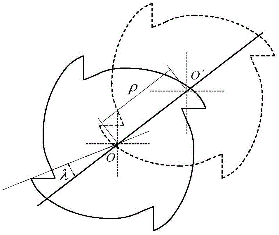
[0056] (2) After the tool is installed, use a dial indicator to measure the deviation between the blade at different axial positions and the rotation center of the tool spindle. Based on this deviation data, refer to figure 1 , to calibrate the tool eccentricity parameters ρ and λ. ρ represents the offset between the tool rotation center O' and the tool geometric center O, and λ represents the angle between the direction of tool eccentricity and...
Embodiment 2
[0081] (1) The verification test selected the radius R as 6mm, the helix angle β as 31°, and the normal rake angle α n 15.5°, number of teeth N f A carbide end mill with a value of 3 performs down milling on an aluminum alloy 7050-T7451 in a three-coordinate vertical machining center. Calibration test parameters are tool spindle speed 1300RPM, single tooth feed rate f is 0.1mm / tooth, axial depth of cut a p Equal to 4mm, radial depth of cut a e equal to 6mm.
[0082] (2) After the tool is installed, use a dial indicator to measure the deviation between the blade at different axial positions and the rotation center of the tool spindle. Based on this deviation data, refer to figure 1 , to calibrate the tool eccentricity parameters ρ and λ. The results were ρ=0.009mm, λ=62.1°.
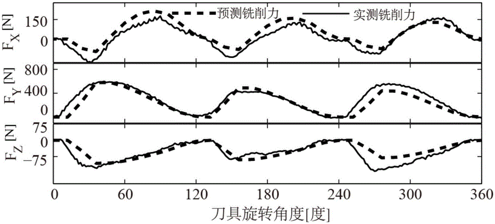
[0083](3) According to the cutting parameters set in step (1) and measuring the milling force, it is required that the machined surface of the workpiece is perpendicular to the axis of the tool. use ...
Embodiment 3
[0101] Adopt the shear force coefficient K that calibration obtains in embodiment 2 Ts , K Rs , K As , Coefficient of plowing force K sp,T , K sp,R , K sp,A , brought into literature 3 "C.Eksioglu, Z.M.Kilic, Y.Altintas, Discrete-time prediction of chatterstability, cutting forces, and surface location errors inflexible milling systems, Transactions of the ASME Journal of Manufacturing Science and Engineering 134 (2012) 061006" to obtain the stability prediction algorithm of leaflets considering cutting damping The results are shown and verified experimentally. From Figure 4 It can be seen that the stable cutting process obtained by the experimental test is basically located in the stable region below the lobe diagram, the experimentally determined critical stable cutting is in the area near the lobe diagram, and the measured flutter cutting is basically located in the unstable region above the lobe diagram. It shows that the predicted results are in good agreement with...
PUM
 Abstract
Description
Claims
Application Information
 - R&D
- Intellectual Property
- Life Sciences
- Materials
- Tech Scout
- Unparalleled Data Quality
- Higher Quality Content
- 60% Fewer Hallucinations
Browse by: Latest US Patents, China's latest patents, Technical Efficacy Thesaurus, Application Domain, Technology Topic, Popular Technical Reports.
© 2025 PatSnap. All rights reserved.Legal|Privacy policy|Modern Slavery Act Transparency Statement|Sitemap|About US| Contact US: help@patsnap.com


