Orientation equipment, orientation film preparation method and display substrate
A technology for display substrates and alignment films, which can be applied to opto-mechanical equipment, photo-engraving processes on patterned surfaces, and devices for coating liquids on surfaces, etc., and can solve the problems of easy peeling, poor frame, and low control accuracy of alignment films. , to achieve the effect of overcoming peeling, simple transformation, and increasing edge control accuracy
- Summary
- Abstract
- Description
- Claims
- Application Information
AI Technical Summary
Problems solved by technology
Method used
Image

Examples
Embodiment 1
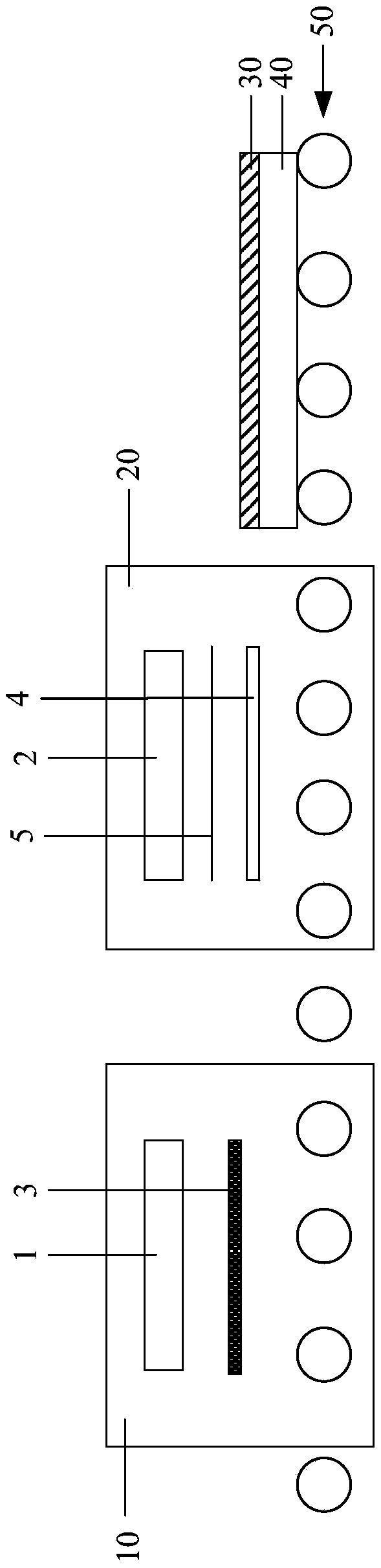
[0034] Such as figure 1 As shown, the alignment equipment in this embodiment is used to align the alignment area of the alignment film 30 . The alignment film 30 is formed on the display substrate 40 , and the alignment area of the alignment film 30 corresponds to the position of the display area of the display substrate 40 to provide a certain pretilt angle for the liquid crystal molecules. The alignment film 30 also includes a non-alignment area located around the alignment area.
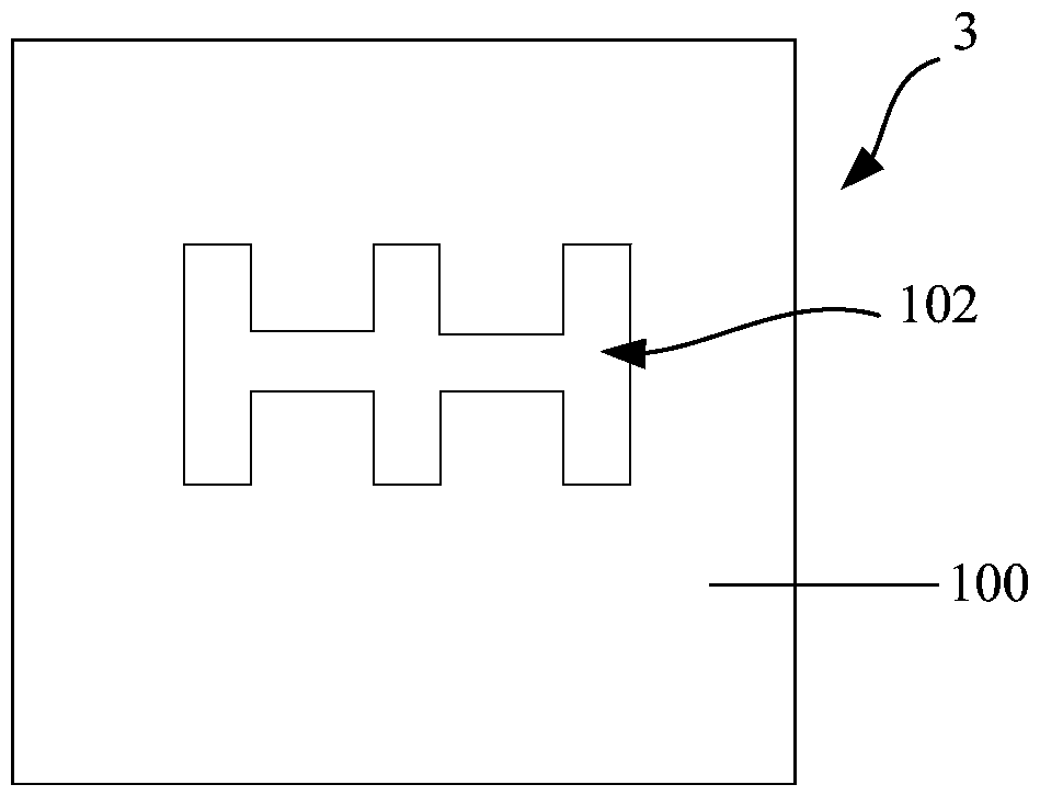
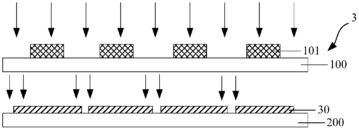
[0035] The alignment equipment includes a first exposure chamber 10 for removing an alignment film 30 in a non-alignment area. The first exposure chamber 10 includes a first lamp box 1 and a shading plate 3. The shading plate 3 is used to block light from irradiating the alignment area of the alignment film 30. The light emitted by the first light box 1 is used to expose the non-alignment area to remove the non-alignment area. The alignment film in the alignment area increases the edge c...
Embodiment 2
[0052] see figure 1 As shown, a display substrate 40 is provided in this embodiment, including a display area and a non-display area located around the display area. The display substrate 40 includes an alignment film 30, and the alignment film 30 corresponds to the display area of the display substrate 40, that is, the alignment film only includes an alignment area. In the manufacturing process, the alignment film 30 in the non-alignment area is removed, thereby increasing the alignment film 30. Edge control accuracy, and the process is simple, without debugging.
[0053] The display substrate 40 may be an array substrate or a color filter substrate of a liquid crystal display device, or other display substrates with an alignment film.
[0054] In this embodiment, for the array substrate and the color filter substrate, when the alignment film on them only includes the alignment area, after the two are boxed, the sealant does not overlap with the alignment film, which overc...
Embodiment 3
[0057] This embodiment provides a method for preparing an alignment film using the alignment device in Embodiment 1, the alignment film includes an alignment area and a non-orientation area located at the periphery of the alignment area, and the preparation method includes aligning the alignment film. The step of aligning the region, the preparation method further includes the step of removing the alignment film of the non-aligned region.
[0058] The alignment film prepared by the above manufacturing method only includes the alignment area, and the peripheral non-alignment area is removed, thereby increasing the edge control accuracy of the alignment film. Since only the step of removing the alignment film in the non-alignment area needs to be added, the process is simple, no debugging is required, and the cost is low. For the array substrate and the color filter substrate, when the alignment film is formed on it by the above-mentioned manufacturing method, the sealant does n...
PUM
 Abstract
Description
Claims
Application Information
 - Generate Ideas
- Intellectual Property
- Life Sciences
- Materials
- Tech Scout
- Unparalleled Data Quality
- Higher Quality Content
- 60% Fewer Hallucinations
Browse by: Latest US Patents, China's latest patents, Technical Efficacy Thesaurus, Application Domain, Technology Topic, Popular Technical Reports.
© 2025 PatSnap. All rights reserved.Legal|Privacy policy|Modern Slavery Act Transparency Statement|Sitemap|About US| Contact US: help@patsnap.com