Micro-motion device module

A micro-motion device and lens technology, applied in installation, optics, instruments, etc., can solve problems such as low production efficiency, high difficulty, complex assembly of optical and mechanical parts, etc., to reduce investment, avoid appearance, improve production efficiency and excellent rate effect

Inactive Publication Date: 2016-04-20
ANHUI CHANGSHUO PHOTOELECTRIC TECH CO LTD
View PDF4 Cites 0 Cited by
  • Summary
  • Abstract
  • Description
  • Claims
  • Application Information

AI Technical Summary

Problems solved by technology

[0004] In order to solve the problems of complex and difficult assembly of the optical and mechanical parts of the above-mentioned micro-motion device module and low production efficiency, the present invention provides a micro-motion device module

Method used


Image

  • Micro-motion device module
  • Micro-motion device module
  • Micro-motion device module

Examples


Embodiment Construction

[0021] In order to make it easy to understand the technical means, creative features, objectives and effects achieved by the present invention, the present invention will be further explained below in conjunction with specific drawings.

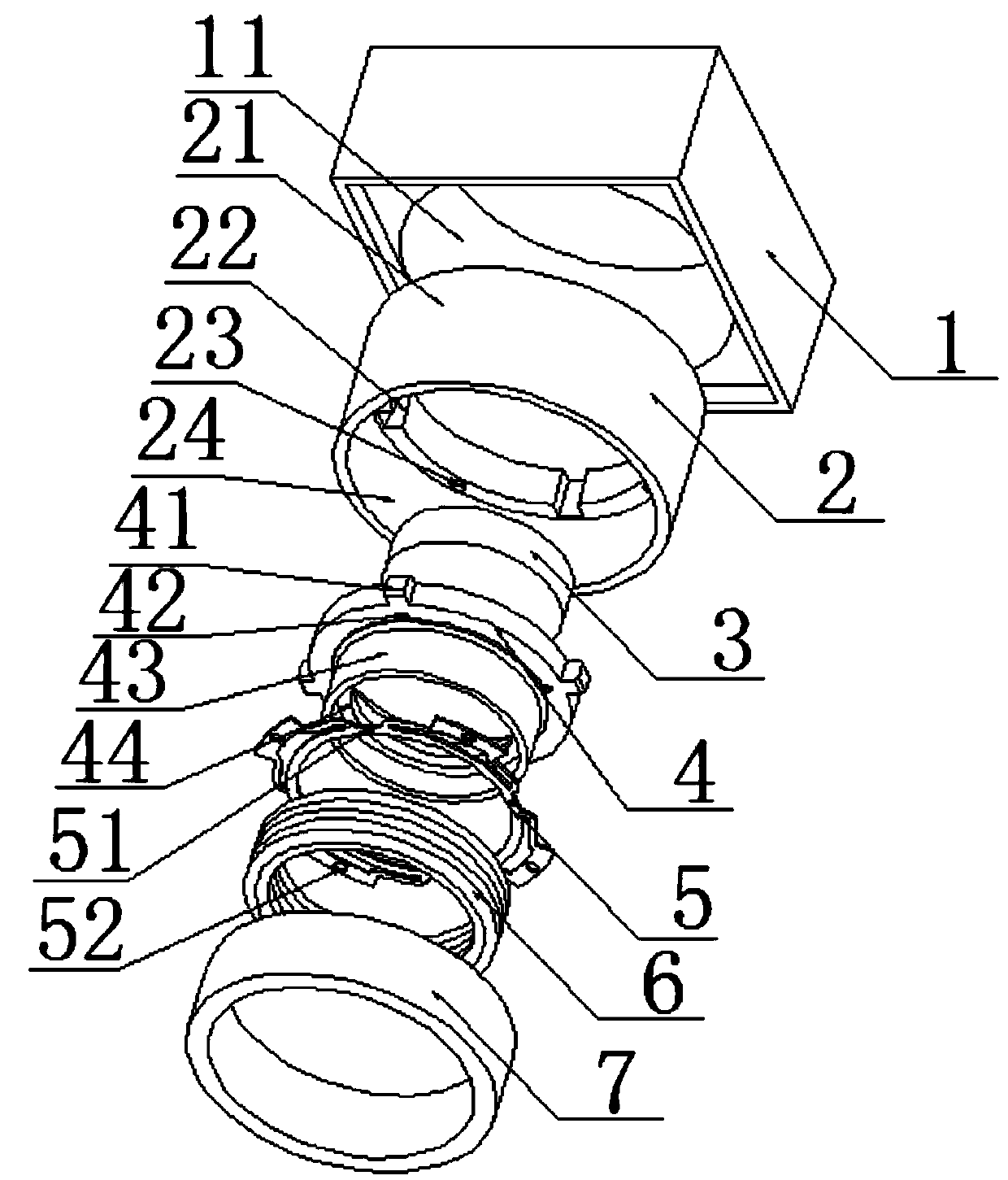
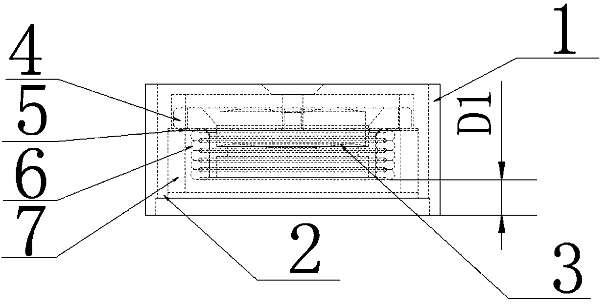
[0022] Combine figure 1 Shown is a three-dimensional exploded schematic diagram of one of the structures used to realize the micro-motion device of the present invention. The main components used in the invention include square shell 1, round shell 2, lens 3, lens holder 4, shrapnel 5, coil 6 and magnetic ring 7. The inner surface of the square shell 1 and the outer surface of the round shell 2 are fixed together; the lens 3 is embedded on the lens holder 4; the elastic sheet 5 connects the lens holder 4 and the round shell 2; the coil 6 is fixed on the outside of the lens holder 4 Surface; the magnetic ring 7 is fixed on the inner surface of the circular shell 2. The square shell and the round shell are connected by glue fastening. The square...


PUM


Abstract

The invention discloses a micro-motion device module, and relates to the technical field of optical module manufacturing. The module comprises a square shell, a round shell, a lens, a lens holder, an elastic sheet, a coil and a magnetic ring. The inner surface of the square shell and the outer surface of the round shell are fixed together. The lens is embedded into the lens holder. The elastic sheet connects the lens holder and the round shell. The coil is fixed on the outer surface of the lens holder. The magnetic ring is fixed on the inner surface of the round shell. According to the micro-motion device module, an optical structure and a mechanical structure are combined together, undesirable exterior and optical phenomena are avoided, the number of production steps and the labor investment are reduced, the production efficiency and the rate of qualified products are improved, and the cost is lowered.

Description

Technical field [0001] The present invention relates to the technical field of optical module production and manufacturing, in particular to a micro-motion device module. Background technique [0002] In recent years, the application of optical modules has become more and more extensive, such as mobile phones, computers and cameras, which are closely related to our electronic products. With the increasing use of these products, the rapid development of the optical module manufacturing industry has been promoted. In addition to the image processor, the micro-motion device module is also important to determine the image quality of the optical module during viewfinder. [0003] At present, the most commonly used micro-motion device module in production is a structure designed separately for the optical structure part and the mechanical structure part. During the production process, the two need to be assembled manually or by other means. During the assembly process, a lot of manpower ...

Claims


Application Information

Patent Timeline
IPC IPC(8): G02B7/02G02B7/00
Inventor 鲁大鹏李守鑫
Owner ANHUI CHANGSHUO PHOTOELECTRIC TECH CO LTD
Why Eureka
Try Eureka