Low-temperature ultrasonic vibration fatigue experiment system
An ultrasonic vibration and fatigue experiment technology, which is applied in the direction of analyzing solids, analyzing materials, and instruments using sound waves/ultrasonic waves/infrasonic waves, can solve problems such as inability to accurately simulate fatigue loading, and achieve reduced environmental temperature unevenness, uniform temperature, and reduced The effect of energy consumption
- Summary
- Abstract
- Description
- Claims
- Application Information
AI Technical Summary
Problems solved by technology
Method used
Image
Examples
Embodiment 1
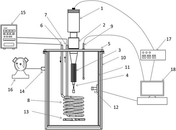
[0037] Such as Figure 1 to Figure 4 As shown, a low-temperature ultrasonic vibration fatigue experiment system includes a piezoelectric transducer 1 and an ultrasonic signal generator 17. The electrical energy input end of the piezoelectric transducer 1 and the alternating current signal output end of the ultrasonic signal generator 17 Electrically connected, a test piece 4 is connected to the mechanical vibration output end of the piezoelectric transducer 1;
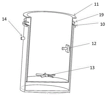
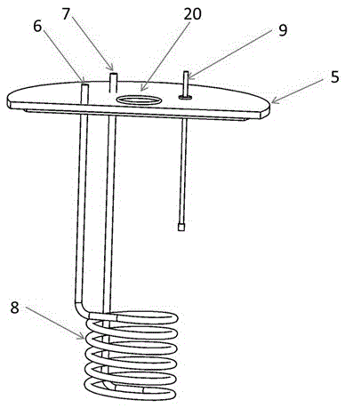
[0038] It also includes a low-temperature box, the low-temperature box is a closed box structure, the test piece 4 is located in the low-temperature box, a cooler 8 is also provided in the low-temperature box, and a cooling device 15 is also provided outside the low-temperature box, so The cooling device 15 is connected to the cooler 8 through a pipeline;
[0039] The cooler 8 has a spiral disk tubular structure, and the reciprocating direction of the test piece 4 is located on the axis of the spiral disk tubular structure...
Embodiment 2
[0047] Such as Figure 1 to Figure 4 As shown, this embodiment is further limited on the basis of Embodiment 1: Since no matter single crystal or ceramic material is used in the existing piezoelectric transducer 1, the mechanical deformation displacement obtained is very small, such as only a few microns, In order to amplify the above displacement and obtain a more accurate measurement value, a displacement amplifier 2 is also connected to the mechanical vibration output end of the piezoelectric transducer 1, and the test piece 4 is connected to the displacement amplifier 2. The displacement amplifier 2 realizes the amplification of vibration displacement based on the different displacements of different parts during resonance. The more commonly used shapes are: exponential, conical, stepped displacement amplifier2.
[0048] Since the piezoelectric transducer 1 and the displacement amplifier 2 both generate heat during operation, in order to avoid or reduce the influence of the ...
Embodiment 3
[0054] Such as Figure 1 to Figure 4 As shown, this embodiment is further limited on the basis of any one of the technical solutions provided in the above embodiments: in order to enable the system to realize the vibration fatigue test of the specimen 4 in a low temperature and vacuum environment, and realize vacuum insulation at the same time, which is beneficial to isolation Thermal effect to improve the temperature control accuracy of the test piece 4 and obtain more accurate low-temperature vibration fatigue test values. The low-temperature box is also provided with a vacuum interface 14 which is connected to the outside of the low-temperature box through a pipe The vacuum pump 16. This solution also has the purpose of reducing the amount of cooling medium and reducing energy consumption.
[0055] As a specific implementation scheme for improving the experimental efficiency of the system, the ultrasonic signal generator 17 is an ultrasonic signal generator that can output an...
PUM
| Property | Measurement | Unit |
|---|---|---|
| diameter | aaaaa | aaaaa |
| thickness | aaaaa | aaaaa |
| diameter | aaaaa | aaaaa |
Abstract
Description
Claims
Application Information
 - R&D
- Intellectual Property
- Life Sciences
- Materials
- Tech Scout
- Unparalleled Data Quality
- Higher Quality Content
- 60% Fewer Hallucinations
Browse by: Latest US Patents, China's latest patents, Technical Efficacy Thesaurus, Application Domain, Technology Topic, Popular Technical Reports.
© 2025 PatSnap. All rights reserved.Legal|Privacy policy|Modern Slavery Act Transparency Statement|Sitemap|About US| Contact US: help@patsnap.com


