A Drilling and Measuring Integrated Device Based on Stress Relief Method

A stress relief method and drilling and testing technology, applied in surveying, drilling equipment, earthwork drilling, etc., can solve the problems of complicated testing process and hinder application, and achieve the effect of simple structural system, reduced requirements, and simple mechanical structure

Active Publication Date: 2016-11-02
INST OF ROCK & SOIL MECHANICS CHINESE ACAD OF SCI
View PDF5 Cites 0 Cited by
  • Summary
  • Abstract
  • Description
  • Claims
  • Application Information

AI Technical Summary

Problems solved by technology

The usual operation steps on site are as follows: First, drill a larger hole at the place where the ground stress needs to be measured. After drilling to a certain depth, replace the drill bit to smooth the bottom of the hole, and then change a wedge-shaped drill bit to drill a trumpet hole ( guide), then replace the small drill bit and the drill pipe, drill a small measurement hole in the center of the large hole, then lift the drill pipe, install the measurement sensor in the measurement hole, the sensor leads pass through all the drill pipes, and then the large drill bit continues Drilling to complete stress relief drilling; the equipment installation and testing process of the entire stress relief method is relatively complicated, including large hole drilling, hole bottom grinding, pilot hole formation, measurement hole drilling, sensor layout, and relief holes There are multiple steps such as drilling, and each step requires the drilling rig to cooperate with lifting and lowering the drill pipe to realize the replacement of the drill bit. In particular, the lead wire problem when the sensor is laid seriously hinders the application of this method in deep holes, making the stress relief method often limited to Testing in Shallow Holes

Method used


Image

  • A Drilling and Measuring Integrated Device Based on Stress Relief Method
  • A Drilling and Measuring Integrated Device Based on Stress Relief Method
  • A Drilling and Measuring Integrated Device Based on Stress Relief Method

Examples


Embodiment Construction

[0039]Below in conjunction with accompanying drawing and implementation example, the present invention is further described:

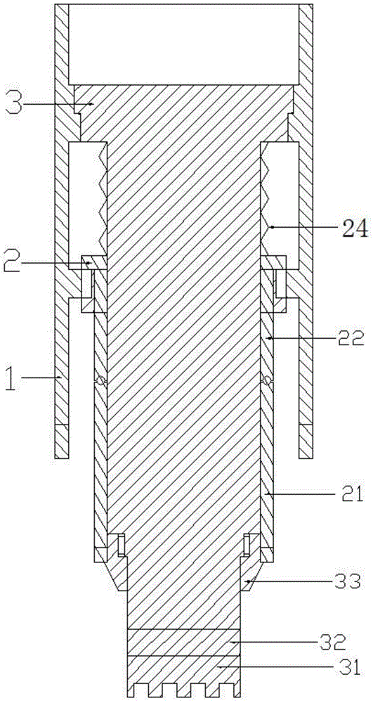
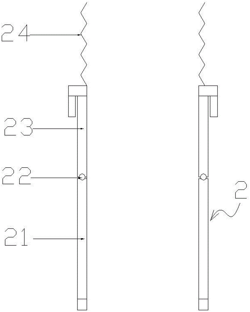
[0040] An integrated device for drilling and measuring based on a stress relief method, comprising a cylindrical relief hole drill part 1, a detachment control part 2 and a measuring hole drill part 3,

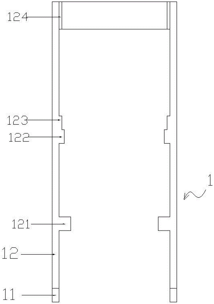
[0041] The hole-releasing drill bit part 1 includes a cylindrical drill rod 12, the inner side of the drill rod 12 is provided with a transmission tooth 121, and the bottom of the drill rod 12 is provided with a hole-releasing drill bit 11,

[0042] The measuring hole drill bit part 3 includes a cylindrical casing 34 , an annular positioning part 36 is sleeved on the casing 34 , and a guide groove 343 is formed on the outer side of the annular positioning part 36 along the longitudinal direction of the casing 34 , and the guide groove 343 penetrates through the annular positioning part 36 . On the upper and lower surfaces, the outer side of the annular...


PUM


Abstract

The invention discloses a drilling and measuring integrated device based on a stress relief method. The drilling and measuring integrated device comprises a tubular relief hole drill bit part, a breakaway control part and a measuring hole drill bit part. The relief hole drill bit part comprises a tubular drill rod, transmission teeth are arranged on the inner side of the drill rod, a relief hole drill bit is arranged at the bottom of the drill rod, the measuring hole drill bit part comprises a columnar shell, an upper sleeve of the shell is provided with an annular positioning portion while the bottom of the same is provided with a measuring hole drill bit, a wedge-shaped drill bit sleeves the upper portion of the measuring hole drill bit and comprises a tubular connecting column and a conical head below the connecting column, the breakaway control part comprises a limiting ring, an upper limiting plug-pin and a short limiting plug-pin, and the upper limiting plug-pin and the short limiting plug-pin are arranged on the limiting ring. By the drilling and measuring integrated device, drilling and measuring integration can be realized, the problem that the stress relief method is complex in operation process and low in measuring depth is solved, testing capability is improved remarkably, and requirements on testing environment are lowered remarkably.

Description

technical field [0001] The invention relates to the field of drilling and surveying, in particular to an integrated drilling and surveying device based on a stress relief method, which is suitable for stress relief. Background technique [0002] In-situ stress exists widely, but it is difficult to obtain and reveal. At the same time, it plays an important role in the planning, design and decision-making of deep engineering. With the continuous exploration of the deep crust by human beings, the importance of in-situ stress has become increasingly apparent. At present, the research on the principle, technology and method of geostress measurement is deepening, and the corresponding measuring instruments and equipment are constantly emerging, which creates conditions for the breakthrough of geostress testing technology. [0003] Human's understanding of in-situ stress first appeared in the early 20th century, while the actual measurement of in-situ stress began in the 1930s. W...

Claims


Application Information

Patent Timeline
Patent Type & Authority Patents(China)
IPC IPC(8): E21B47/00E21B7/00
CPCE21B7/00E21B47/00
Inventor 王川婴汪进超韩增强胡胜
Owner INST OF ROCK & SOIL MECHANICS CHINESE ACAD OF SCI
Why Eureka
Try Eureka