
Optical film with adhesive and production method thereof, and method for producing image display device

A technology for image display devices and optical films, applied in adhesive types, chemical instruments and methods, ester copolymer adhesives, etc., can solve problems such as uneven display, achieve pollution suppression, low fluidity, and display suppression uneven effect

Active Publication Date: 2016-04-20
NITTO DENKO CORP
View PDF7 Cites 8 Cited by
  • Summary
  • Abstract
  • Description
  • Claims
  • Application Information

AI Technical Summary

Problems solved by technology

In addition, pressure is applied to the image display panel immediately below the printed height difference through the adhesive, and mechanical strain is generated at the edge of the screen, which may cause problems such as display unevenness at the periphery of the screen.

Method used


Image

  • Optical film with adhesive and production method thereof, and method for producing image display device
  • Optical film with adhesive and production method thereof, and method for producing image display device
  • Optical film with adhesive and production method thereof, and method for producing image display device

Examples


Embodiment 1

[0148]

[0149] The pressure-sensitive adhesive sheet X was bonded to one surface of the polarizing plate as a cell-side pressure-sensitive adhesive layer. Then, the pressure-sensitive adhesive sheet A was bonded on the other surface of the polarizing plate as a visible-side pressure-sensitive adhesive layer. In this way, an adhesive sheet X with a thickness of 20 μm was attached to one side of a polarizing plate, an adhesive sheet A with a thickness of 150 μm was attached to the other side, and a separator was attached to each adhesive sheet in a releasable manner. A polarizing plate with an adhesive on both sides of the sheet. This double-sided adhesive-attached polarizing plate was punched out to a size of 50 mm×80 mm using a Thomson knife. After 50 sheets of punched double-sided polarizing plates with adhesive are stacked, use a hand-held UV lamp (energy density of UVA: 300mW / cm 2 ) Irradiated from the side of the polarizing plate with a cumulative light intensity of a...

Embodiment 2~4

[0154] A polarizing plate with an adhesive on both sides was produced in the same manner as in Example 1 except that the PSA sheets B to D were used as the visible-side pressure-sensitive adhesive layer, and an image display device was produced in the same manner as in Example 1.


PUM

PropertyMeasurementUnit
thicknessaaaaaaaaaa
thicknessaaaaaaaaaa
thicknessaaaaaaaaaa

Abstract

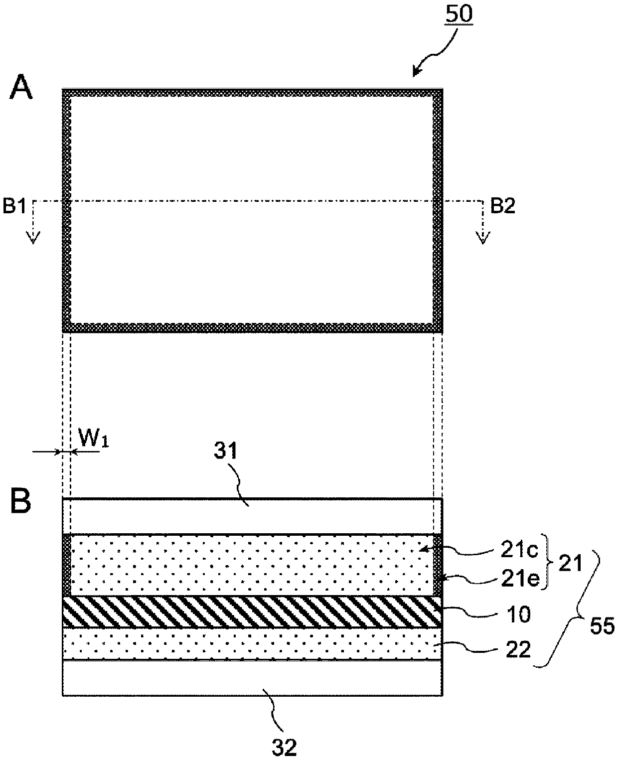
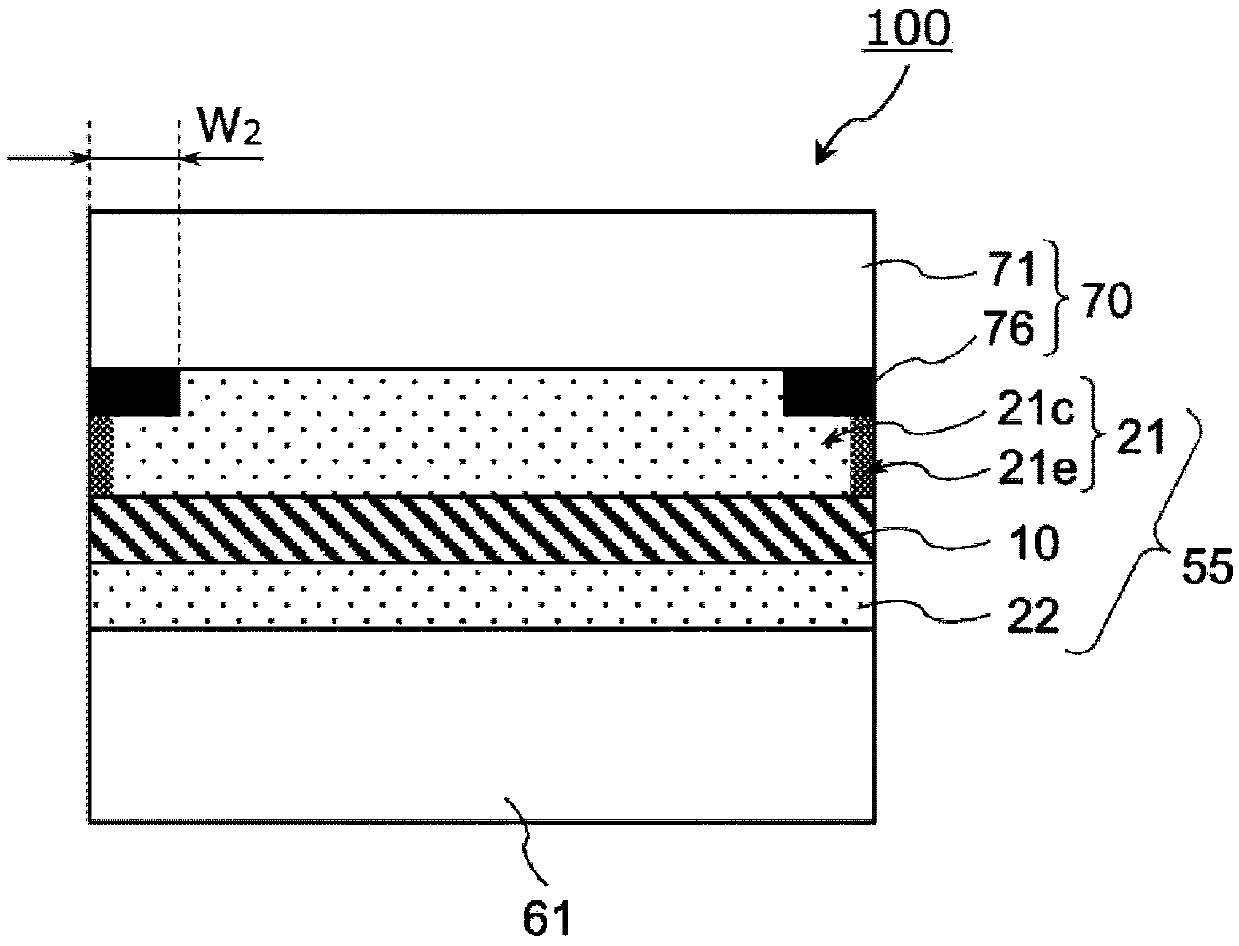
The invention relates to an optical film with an adhesive and a production method thereof, and a method for producing an image display device. The invention provides an adhesive sheet which can suppress display uneveness of the image display device when the optical film is disposed between a front transparent plate or a touch panel and an image display panel and has the adhesive protrude from an end face, and the optical film with the adhesive sheet, and the image display device. In the adhesive sheet with the adhesive, a main face of the optical film (10) comprising a polarization board includes an adhesive layer (21) for adhesion to the front transparent plate or the touch panel. The adhesive layer (21) has a thickness more than 30 [mu]m, and fluidity of the adhesive (21e) at an end surface is lower than a fluidity of the adhesive (21c) at an in-plane central part. The optical film with the adhesive is configured as the optical film (10), the second main face of which has an optical film with a double-face adhesive of an adhesive layer (22) for adhesion to the image display unit.

Description

technical field [0001] The present invention relates to an adhesive-attached optical film for forming an image display device having a transparent plate, a touch panel, etc. on the front surface of an image display panel, and a method for producing the same. In addition, the present invention relates to a method of producing an image display device using the adhesive-attached optical film. Background technique [0002] Liquid crystal display devices and organic electroluminescence display devices are widely used as various image display devices such as mobile phones, car navigation devices, computer monitors, and televisions. In order to prevent damage to the image display panel due to impact from the outer surface of the image display panel (liquid crystal panel or organic electroluminescent panel), sometimes a transparent resin plate or a glass plate is provided on the visible side of the image display panel. Transparent panels (also known as "window layers", etc.). [0...

Claims


Application Information

Patent Timeline
Patent Type & Authority Applications(China)
IPC IPC(8): C09J7/02C09J133/08G02B5/30C09J7/22C09J7/38
CPCC09J133/066B32B37/003B32B37/182B32B2037/1253B32B2307/412C09J2203/318C09J7/38C09J7/22C09J2433/00B32B2307/42B32B2457/20C09J2301/1242C09J2301/312C09J133/08
Inventor 宝田翔水谷昌纪保井淳
Owner NITTO DENKO CORP
Learn More