Clip hole structure

A technology of hole structure and clips, which is applied in vehicle safety arrangements, radiators, transportation and packaging, etc., can solve problems such as large insertion force, difficulty in disassembly, breakage, etc., achieves easy assembly and disassembly, reduces difficulty in disassembly, and saves costs Effect

Inactive Publication Date: 2016-04-20
CHENGDU AEROSPACE MOLD & PLASTIC CO LTD
View PDF0 Cites 0 Cited by
  • Summary
  • Abstract
  • Description
  • Claims
  • Application Information

AI Technical Summary

Problems solved by technology

[0003] The technical problem to be solved by the present invention is: the existing buckle structure causes the clip 3 to be assembled with a relatively large insertion force, difficult to disassemble, and prone to breakage, deformation and damage

Method used


Image

  • Clip hole structure
  • Clip hole structure
  • Clip hole structure

Examples


Embodiment Construction

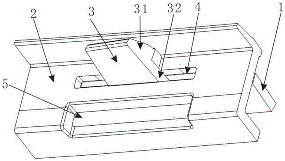
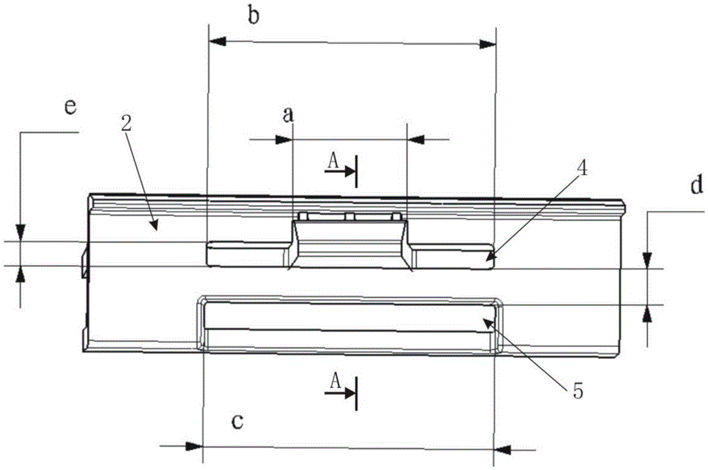
[0021] Such as figure 2 The clip hole structure includes a clip mounting hole 4 of a rectangular structure inserted into and clamping the clip 3, and the clip mounting hole 4 is arranged on the clip attachment 1. Compared with the existing clip hole structure, the clip hole structure also includes a clip mounting hole 4 disposed on one side of the deformation direction of the clip mounting hole 4 on both sides of the deformation direction, and a deformation hole 5 with a certain distance from the clip mounting hole 4, This distance is named in the present invention. Certainly, if necessary, for example, when the material is relatively hard and the amount of deformation is insufficient, it is also feasible to respectively set a deformation hole 5 on both sides of the deformation direction of the clip mounting hole 4 .

[0022] The deformation direction of the clip mounting hole 4 is its first direction.

[0023] In this embodiment, the deformation hole 5 is a rectangular h...


PUM


Abstract

The invention discloses a clip hole structure. The clip hole structure comprises a clip installing hole into which a clip is inserted and clamped and a deforming hole or deforming holes, wherein the clip installing hole is of a rectangular structure; the clip installing hole is formed in a clip attachment piece; the deforming hole is formed in one side of a deforming direction of the clip installing hole or the deforming holes are respectively formed in two sides of the deforming direction of the clip installing hole; the deforming hole or the deforming holes is or are in a certain distance from the clip installing hole. According to the clip hole structure disclosed by the invention, double-hole structure optimization on a clip hole is adopted, and one deforming hole is additionally formed in one side of the deforming direction of the clip installing hole or two deforming holes are respectively and additionally formed in the two sides of the deforming direction of the clip installing hole, so that the problem of assembling and disassembling difficulty caused by deforming difficulty of a clip installing hole of an existing similar clip is solved, assembling and disassembling can be easier, the productivity is increased, a risk that one product is scrapped together with the other one because the two products in which the clip and the clip hole are arranged cannot be separated due to disassembling difficulty can be reduced, and the recovery rate of the products is increased; meanwhile, the products are lighter because certain materials are reduced, and the cost is saved.

Description

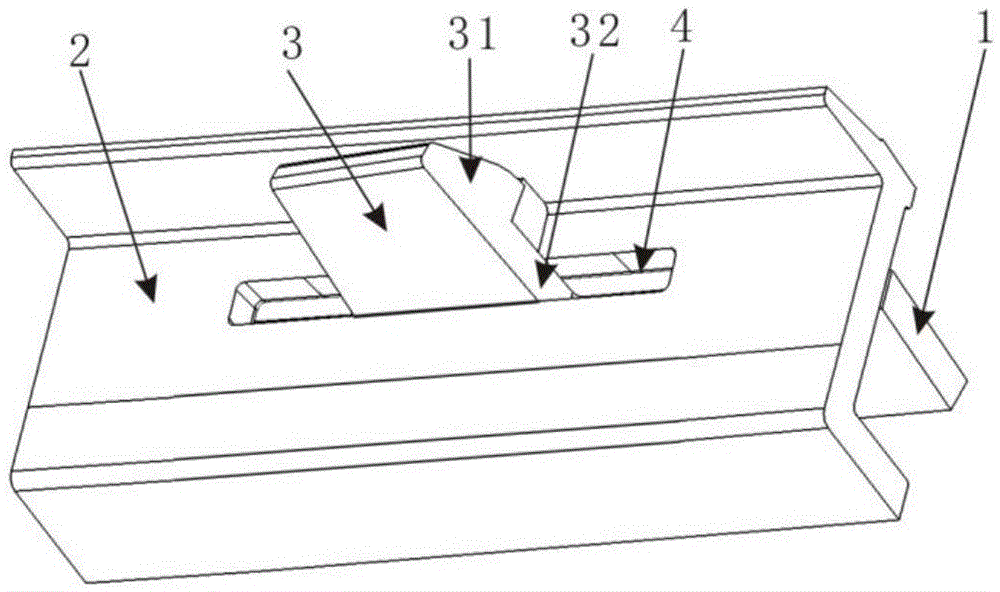
technical field [0001] The invention relates to the technical field of clips, in particular to a clip hole with a deformation hole. Background technique [0002] At present, the existing clip buckle structure (such as figure 1 ), the clip 3 is made up of a clip head 31 of a wedge-shaped body structure and a clip wall 32 thereunder, the clip hole has only a clip mounting hole 4 of a rectangular structure, and when the clip head 31 is inserted into the clip mounting hole 4, the clip mounting hole 4 is deformed The widening has passed the clip head 31, and after passing through, the clip mounting hole 4 returns to its original shape. The existing clip buckle structure has the following problems during disassembly: since there is only one clip installation hole 4 in the clip hole, and the surroundings of the clip installation hole 4 are closed structures, the deformation of the clip installation hole 4 is relatively difficult, resulting in relatively high insertion and withdraw...

Claims


Application Information

Patent Timeline
Patent Type & Authority Applications(China)
IPC IPC(8): B60R19/52
CPCB60R19/52B60R2019/527
Inventor 汪会周鹏黄崇邦文化
Owner CHENGDU AEROSPACE MOLD & PLASTIC CO LTD
Why Eureka
Try Eureka