
Automatic flaring machine

A flaring machine and automatic technology, applied in the direction of metal processing equipment, feeding devices, manufacturing tools, etc., can solve the problems of inability to guarantee positioning accuracy, poor consistency of finished products, and low qualified rate of finished products, so as to improve positioning accuracy, The effect of reducing production costs and labor intensity

Active Publication Date: 2017-11-17
GREE ELECTRIC APPLIANCES INC
View PDF6 Cites 0 Cited by
  • Summary
  • Abstract
  • Description
  • Claims
  • Application Information

AI Technical Summary

Problems solved by technology

At present, most of the stamping and flaring work is that the operator sends a single connecting pipe into the flaring machine. During the stamping and flaring process, the connecting pipe is manually positioned, which cannot guarantee the accuracy of the positioning, resulting in a low pass rate of finished products and also Resulting in less consistent finished product
[0003] In addition, the existing flaring machines perform stamping and flaring through manual foot switches, resulting in low production efficiency and high labor intensity

Method used


Image

  • Automatic flaring machine
  • Automatic flaring machine
  • Automatic flaring machine

Examples


Embodiment Construction

[0042] The following will clearly and completely describe the technical solutions in the embodiments of the present invention with reference to the accompanying drawings in the embodiments of the present invention. Obviously, the described embodiments are only some, not all, embodiments of the present invention. Based on the embodiments of the present invention, all other embodiments obtained by persons of ordinary skill in the art without making creative efforts belong to the protection scope of the present invention.

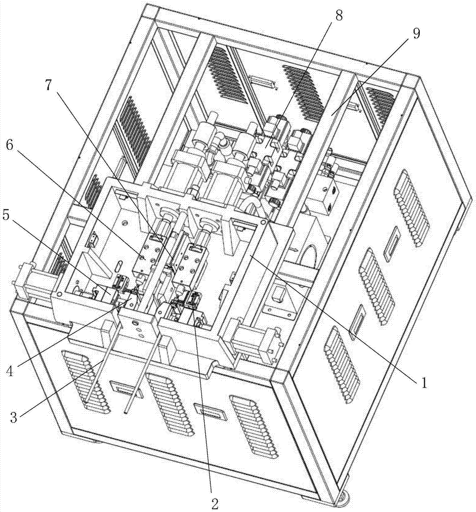
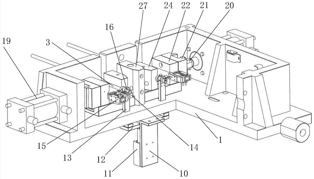
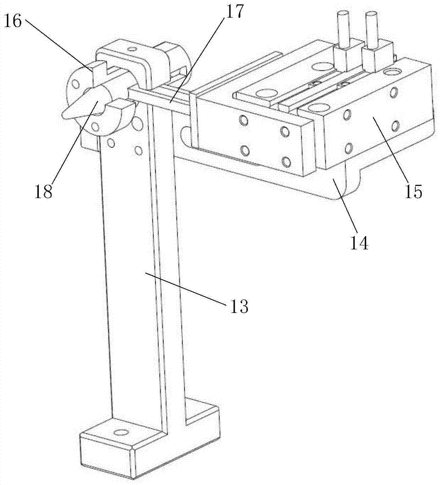
[0043] Such as figure 1 As shown, the automatic flaring machine provided by the embodiment of the present invention includes: a machine base 1, a flaring fixed die assembly 4, a flaring movable die assembly 5, a flaring stamping device 6 and a positioning device 2; wherein, the flaring The fixed die assembly 4, the flared movable die assembly 5, the flared stamping device 6 and the positioning device 2 are all arranged on the base 1, and the flared movable die...


PUM


Abstract

The invention discloses an automatic flaring machine which comprises a machine base, a flaring fixed die assembly, a flaring movable die assembly, a flaring and stamping device and a positioning device, wherein the flaring movable die assembly is matched with the flaring fixed die assembly to clamp connection pipes; the flaring and stamping device is used for conducting flaring on the connection pipes; the positioning device can make the axes of the connection pipes coincide with the axis of a punch of the flaring and stamping device; the flaring fixed die assembly, the flaring movable die assembly, the flaring and stamping device and the positioning device are arranged on the machine base. According to the automatic flaring machine, the positioning device is additionally arranged, it is guaranteed that the axels of the connection pipes are collinear with the axis of the punch of the flaring and stamping device, and the flaring fixed die assembly and the flaring movable die assembly clamp the connection pipes; compared with the prior art that the connection pipes are manually positioned, positioning accuracy of the connection pipes is effectively improved, so that the percentage of pass of finished products is raised, and consistency of the finished products is improved; the production cost of the finished products is further lowered; meanwhile, automatic flaring is achieved, production efficiency is improved, and labor intensity is lowered.

Description

technical field [0001] The invention relates to the technical field of air-conditioning connecting pipe flaring, and more specifically relates to an automatic flaring machine. Background technique [0002] The connecting pipe of the air conditioner is usually a copper pipe, and the connecting pipe needs to be stamped and flared before connection. At present, most of the stamping and flaring work is that the operator sends a single connecting pipe into the flaring machine. During the stamping and flaring process, the connecting pipe is manually positioned, which cannot guarantee the accuracy of the positioning, resulting in a low pass rate of finished products and also Resulting in poor consistency of the finished product. [0003] In addition, the existing flaring machine performs stamping and flaring through manual foot switches, resulting in low production efficiency and high labor intensity. [0004] To sum up, how to improve the positioning accuracy to improve the qual...

Claims


Application Information

Patent Timeline
Patent Type & Authority Patents(China)
IPC IPC(8): B21D41/02B21D43/00
CPCB21D41/02B21D43/003
Inventor 龚志奔刘金平王琳朱鸿彬周灵聪
Owner GREE ELECTRIC APPLIANCES INC
Learn More