A binocular optometry device
A binocular and light source technology, applied in the field of optical measurement, can solve problems such as low accuracy and high refractive error, and achieve the effect of precise diopter
- Summary
- Abstract
- Description
- Claims
- Application Information
AI Technical Summary
Problems solved by technology
Method used
Image

Examples
Embodiment 1
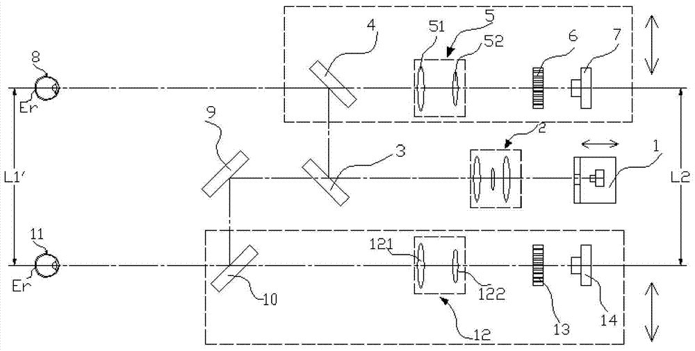
[0053] Such as figure 1 shown.
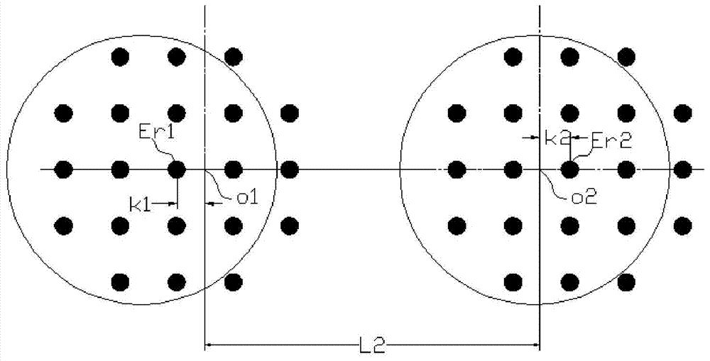
[0054] The light beam emitted by the light source 1 passes through the third lens group 2 composed of several imaging lenses, and then enters the third half-mirror 3, where part of the light beam is reflected by the third half-mirror 3 to form reflected light, and the other A part of the light beam is transmitted through the third half-mirror 3 to form transmitted light. The reflected light is reflected by the first half-mirror 4 to the fundus Er of the first human eye 8 (ie, the upper eye E), and is scattered by the fundus Er, and the reflected light carrying the fundus information of the first human eye 8 is then Return to the first half-mirror 4, transmit to the first lens group 5 through the first half-mirror 4, and finally image on the first imaging unit 7 through the first microlens array 6 to obtain the first person The first dot matrix diagram of the reflected light of the fundus Er of eye 8, see figure 2 Er1 in. The transmitted li...
Embodiment 2
[0070] Such as image 3 As shown, the light beam emitted by the light source 1 passes through the third lens group 2 composed of several imaging lenses, and then enters the third half-mirror 3, and is divided into two parts of the light beam, wherein a part of the light beam passes through the third half-mirror 3 Reflected to the first half mirror 4, another part of the light beam is transmitted to the first mirror 9 through the third half mirror 3. The beam of light reflected to the first half-mirror 4 is reflected by the first half-mirror 4, and is incident on the fundus Er (ie, the eye E above) of the first human eye 8, and is scattered through the fundus Er, carrying The reflected light beam of the fundus information of the first human eye 8 returns to the first half-mirror 4, transmits to the second reflector 15 through the first half-mirror 4, and the second reflector 15 reflects the light beam to the first half-mirror 4. Two reflecting mirrors 16, the light beam passes...
Embodiment 3
[0078] refer to Figure 4 , In this embodiment, the light beam emitted by the light source 1 passes through the third lens group 2 composed of several imaging lenses, and then enters the third half-mirror 3, where a part of the light beam is reflected by the third half-mirror 3 , to form reflected light, and another part of the light beam is transmitted through the third half mirror 3 to form transmitted light. The reflected light is reflected to the first Dove prism 21 through the first half-mirror 4, and after being refracted by the first Dove prism 21, the light beam is incident on the fundus Er of the first human eye 8 (ie, the upper eye E). Scattered by the fundus Er, the reflected light carrying the fundus information of the first human eye 8 returns to the first presbyopic prism 21, and after being refracted by the first presbyopic prism 21, returns to the first half mirror 4, passes through The first half-mirror 4 transmits to the first lens group 5, and finally forms...
PUM
 Abstract
Description
Claims
Application Information
 - R&D
- Intellectual Property
- Life Sciences
- Materials
- Tech Scout
- Unparalleled Data Quality
- Higher Quality Content
- 60% Fewer Hallucinations
Browse by: Latest US Patents, China's latest patents, Technical Efficacy Thesaurus, Application Domain, Technology Topic, Popular Technical Reports.
© 2025 PatSnap. All rights reserved.Legal|Privacy policy|Modern Slavery Act Transparency Statement|Sitemap|About US| Contact US: help@patsnap.com