Filter bags for vacuum cleaners and method for determining the surface area of ​​vacuum cleaner filter bags directly exposed to air flow

A vacuum cleaner and filter bag technology, applied in the field of filter bags, can solve the problems of filter material damage, increase in pressure drop of vacuum cleaner filter bags, and decrease in overall performance of filter bags, and achieve the effect of increasing density

Active Publication Date: 2017-10-10
欧罗菲利特斯公司
View PDF14 Cites 0 Cited by
  • Summary
  • Abstract
  • Description
  • Claims
  • Application Information

AI Technical Summary

Problems solved by technology

[0003] However, this filter bag with few welding points has the disadvantage that the filter material has low mechanical stability, so that the filter material can be damaged at high inflow velocities of the air flow in the vacuum cleaner filter bag
[0006] However, this involves the disadvantage that in the area of ​​the impact protection part, the filter material no longer has any air permeability, so that the pressure drop in the vacuum cleaner filter bag increases
As a result, the storage capacity of the filter material is also drastically reduced, so that the overall performance of the filter bag is significantly reduced
In addition, incoming dust particles are unevenly distributed in the filter bags, which permanently impairs service life

Method used


Image

  • Filter bags for vacuum cleaners and method for determining the surface area of ​​vacuum cleaner filter bags directly exposed to air flow
  • Filter bags for vacuum cleaners and method for determining the surface area of ​​vacuum cleaner filter bags directly exposed to air flow
  • Filter bags for vacuum cleaners and method for determining the surface area of ​​vacuum cleaner filter bags directly exposed to air flow

Examples


Embodiment Construction

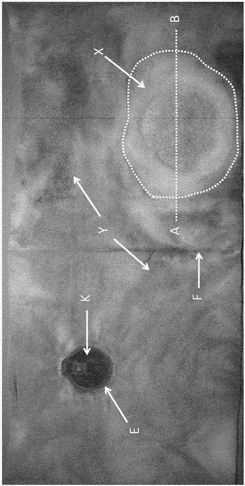
[0086] exist figure 1 In , a vacuum cleaner filter bag implementing the method according to the invention for determining a surface directly exposed to an air flow is shown. Thus, the vacuum cleaner filter bag is a flat bag with welded edges. exist figure 1 , a vacuum cleaner filter bag is shown cut open, whereby the peripheral weld seam previously present at the edge is cut away on three sides, leaving only one weld seam (fold line F). Therefore, the left and right sides shown in the figure represent the front side or the back side of the filter bag. The front side has an inlet opening E with a sealing plate K via which an inlet connection of the vacuum cleaner can be introduced into the vacuum cleaner filter bag. therefore, figure 1 The right hand side shown in (to the right of fold line F) represents the back side of the vacuum cleaner filter bag. exist figure 1 , a view of the inside of a vacuum cleaner filter bag (ie, the inflow side of the filter material) is shown...


PUM

PropertyMeasurementUnit
lengthaaaaaaaaaa
Basis weightaaaaaaaaaa

Abstract

The invention relates to a filter bag for a vacuum cleaner, the filter bag being formed from a filter material comprising at least three layers of filter material. Among the filter material layers, at least one layer is a fabric, and at least one layer is a non-woven fiber layer comprising non-bonded staple fibers and / or non-bonded monofilaments.

Description

technical field [0001] The invention relates to a filter bag for a vacuum cleaner formed of a filter material comprising at least three layers of filter material. Thus, in the case of filter material layers, at least one layer is a fabric layer and at least one layer is a nonwoven fiber layer comprising non-jointed staple fibers and / or non-jointed monofilaments ( filament). The filter bag also includes an inlet opening that allows air to flow into the filter bag. The filter bags according to the invention are distinguished by the fact that in one region of the filter bag, in particular in the region where the air flow entering the filter bag of the vacuum cleaner through the inlet opening directly impinges on the filter material, one or more joints are present, In the joint part, the at least one non-woven fiber layer is joined with at least one of the other two layers, ensuring that the short fibers and / or monofilaments in the non-woven fiber layer are permanently fixed to ...

Claims


Application Information

Patent Timeline
Patent Type & Authority Patents(China)
IPC IPC(8): B01D39/16
CPCB01D2239/065B01D2239/0677B01D2239/0686B01D39/1623B01D46/02
Inventor 拉尔夫·赛耶简·舒尔廷克
Owner 欧罗菲利特斯公司
Why Eureka
Try Eureka