
Monitoring system and method for monitoring the hemodynamic status of a subject

A technology of hemodynamics and monitoring systems, applied in the field of monitoring systems and methods for monitoring the hemodynamic state of objects, capable of solving problems such as reduced reliability, achieving the effects of easy monitoring and increased comfort

Inactive Publication Date: 2016-04-13
KONINKLJIJKE PHILIPS NV
View PDF5 Cites 3 Cited by
  • Summary
  • Abstract
  • Description
  • Claims
  • Application Information

AI Technical Summary

Problems solved by technology

Pulse arrival time is determined as the sum of pre-ejection and pulse transit time, where pre-ejection, isovolumetric systole, can vary independently of blood pressure, making the method less reliable

Method used


Image

  • Monitoring system and method for monitoring the hemodynamic status of a subject
  • Monitoring system and method for monitoring the hemodynamic status of a subject
  • Monitoring system and method for monitoring the hemodynamic status of a subject

Examples


Embodiment Construction

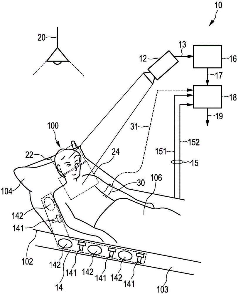
[0041] figure 1 A schematic diagram showing a monitoring system 10 according to the present invention for monitoring the hemodynamic state of a subject 100 such as a patient lying in a bed 102, wherein the head of the subject 100 is positioned on a pillow 104 and the subject 100 Covered by blanket 106 . The system 100 includes: an imaging unit 12 for obtaining a plurality of images 13 of the subject 100 over time; a sensor unit 14 for acquiring sensor signals 15 of the subject 100 related to vital signs of the subject 100; a PPG unit 16 for for generating a photoplethysmographic signal 17 from the plurality of images, that is, a PPG signal 17; and an evaluation unit 18 for jointly evaluating the sensor signal 15 and the PPG signal 17 to extract information about the object 100 Hemodynamic information on the hemodynamic state of the patient 19 .

[0042] In this setup, the imaging unit 12 is mounted remotely, for example at the ceiling or wall of the room in which the bed 102...


PUM


Abstract

The present invention relates to a monitoring system (10) for monitoring the hemodynamic status of a subject (100) comprising an imaging unit (12) for obtaining a plurality of images of the subject (100) over time, a sensor unit (14) for acquiring a sensor signal of the subject (100) related to a vital sign of the subject (100), a PPG unit (16) for generating a photo-plethysmography, PPG, signal from said plurality of images, and an evaluation unit (18) for commonly evaluating said sensor signal and said PPG signal to extract one or more pulse arrival time, PAT, measures and to extract a hemodynamic information about the hemodynamic status of the subject (100) from said one or more PAT measures.

Description

technical field [0001] The present invention relates to a monitoring system and corresponding method for monitoring the hemodynamic state of a subject, in particular to a monitoring system and corresponding method for monitoring changes in blood pressure of a subject such as a patient or a premature infant. The invention also relates to a processor and a corresponding processing method as well as a computer program for implementing said processing method for use in such a monitoring system. Background technique [0002] In the field of medical monitoring systems, there are accelerometers placed at the apex position to detect the patient's pulse and respiration and cuff-based pressure monitors placed at the upper arm and also at the wrist or fingertips Monitoring equipment with photoplethysmographic (PPG) sensors is available. These sensors allow continuous monitoring of the patient. [0003] It has been found that a major problem to be solved by patient monitoring systems ...

Claims


Application Information

Patent Timeline
Patent Type & Authority Applications(China)
IPC IPC(8): A61B5/024A61B5/021
CPCA61B5/02416A61B5/02125A61B5/318A61B5/0002A61B5/02
Inventor J·米尔施泰夫I·O·基伦科
Owner KONINKLJIJKE PHILIPS NV
Learn More