
rice transplanter

A rice transplanter and planting technology, applied in transplanting machinery, agriculture, applications, etc., can solve the problems of unstable rotation of the drive system, phase deviation of acceleration and deceleration, and increase in rotation variation, so as to prevent poor planting and improve the phase. Variation of , the effect of suppressing rotation fluctuations

Inactive Publication Date: 2017-10-24
YANMAR POWER TECHNOLOGY CO LTD
View PDF1 Cites 0 Cited by
  • Summary
  • Abstract
  • Description
  • Claims
  • Application Information

AI Technical Summary

Problems solved by technology

The rotating shaft is repeatedly twisted and twisted, and the backlash of the gears constituting the drive system, the backlash caused by the gap between the parts during the manufacture of the drive system, and the rotation instability of the drive system caused by the torsion of the drive system , so that the rotation fluctuation increases, resulting in the deviation of the acceleration and deceleration phase, resulting in poor implantation

Method used


Image

  • rice transplanter
  • rice transplanter
  • rice transplanter

Examples


Embodiment Construction

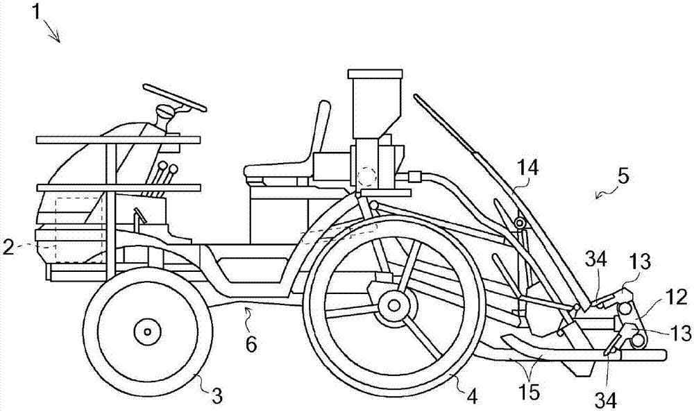
[0033] The rice transplanter 1 is demonstrated with reference to drawings.

[0034] The rice transplanter 1 performs the planting operation by the planting part 5 while driving the front wheel 3 and the rear wheel 4 to travel by the power of the engine 2 . The power from the engine 2 is transmitted to the front wheel 3 and the rear wheel 4 via the transmission case 6, and is transmitted to the planting part 5 via the transmission case 6 and the plant spacing changing device 9, respectively.

[0035] The planting part 5 is provided with the planting center box 10 , the planting bevel gear box 11 , the rotation box 12 , the planting arm 13 , the seedling platform 14 , and the plurality of floating boats 15 .

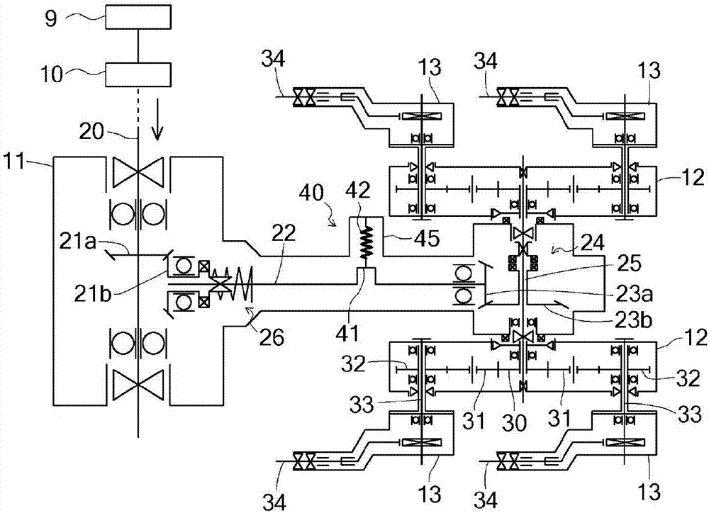
[0036] figure 2 It is a transmission system diagram concerning the planting drive of the planting part 5. figure 2 Although one planting unit is shown, other planting units are configured in the same manner.

[0037] The planting horizontal shaft 20 branched from the ...


PUM


Abstract

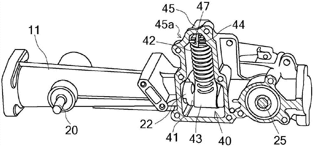
Provided is a rice planting machine that optimizes the trajectory of planting claws and prevents planting errors, by applying torque that negates torque fluctuation occurring in a planting arm shaft, levelling torque fluctuation, and improving phase shift. The planting machine transmits dynamic force via a non-uniform speed mechanism to a planting arm shaft that supports the rotary case and has provided therein a torque-negating mechanism that applies torque that negates torque fluctuation caused by the non-uniform speed mechanism. The torque-negating mechanism has: a crank section wherein part of a planting vertical shaft that transmits dynamic force to the planting arm shaft is formed in a crank shape; and a spring attached to the crank section. Torque is applied by the spring.

Description

technical field [0001] The present invention relates to a rice transplanter. Background technique [0002] In the conventional rice transplanter, if the locus of the tip of the planting claw is set to be almost vertical near the bottom dead center based on dense planting, the speed at which the planting claw leaves the field in the thinning state It becomes slow, so it is easy to cause the phenomenon that the planted seedlings are pushed forward. Conversely, if the locus of the tip of the planting claw is set so that the trajectory of the tip of the planting claw becomes almost vertical near the bottom dead center based on thin planting, in the dense planting state, a phenomenon such as recoil is generated while the planting claw is kept in the field. , and because the seedlings are loose and the soil is dug out, it is easy to cause the seedlings to float. [0003] Therefore, there is a method of providing a non-constant velocity mechanism to make a rotating planting arm s...

Claims


Application Information

Patent Timeline
Patent Type & Authority Patents(China)
IPC IPC(8): A01C11/02
CPCA01C11/003A01C11/006A01C11/02
Inventor 竹山智洋土井邦夫
Owner YANMAR POWER TECHNOLOGY CO LTD
Learn More