
Electric connector and electric connector combination

A technology for electrical connectors and connecting parts, which is applied in the direction of connection, two-part connection device, and parts of the connection device. It can solve problems such as complex assembly and complex structure of EMC iron shell, achieve good shielding effect, and improve grounding signal transmission. , Guarantee the effect of signal transmission effect

Inactive Publication Date: 2016-04-13
ALLTOP ELECTRONICS SU ZHOU +1
View PDF6 Cites 0 Cited by
  • Summary
  • Abstract
  • Description
  • Claims
  • Application Information

AI Technical Summary

Problems solved by technology

However, the structure of the EMC iron shell inside the socket is complicated, and the contact between the EMC iron shell inside the socket and the outer metal shell of the plug requires a preset contact space inside the electrical connector, and the assembly is more complicated

Method used


Image

  • Electric connector and electric connector combination
  • Electric connector and electric connector combination
  • Electric connector and electric connector combination

Examples


Embodiment Construction

[0029] In order to make the object, technical solution and advantages of the present invention clearer, the present invention will be described in detail below in conjunction with the accompanying drawings and specific embodiments.

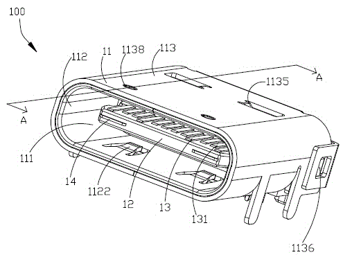
[0030] see figure 1 , Figure 11 as well as Figure 12 As shown, the electrical connector assembly of the present invention includes an electrical connector 100 and a mating electrical connector 200 matched with the electrical connector 100 .

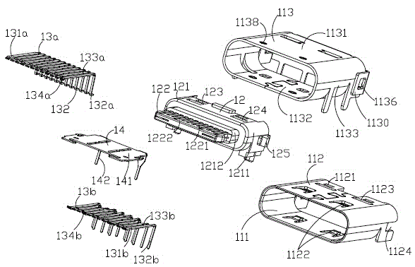
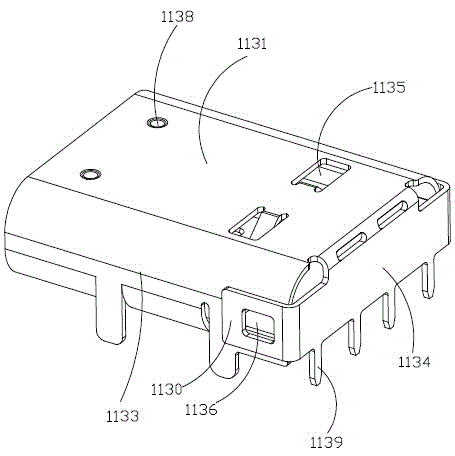
[0031] see Figure 2 to Figure 10 As shown, the electrical connector 100 can be mounted on an external circuit board (not shown) and can be mated with the mating electrical connector 200 . The electrical connector 100 includes a first insulating body 12, a plurality of first terminals 13 fixed in the first insulating body 12, a first ground piece 14 fixed in the first insulating body 12, and a plurality of first terminals 13 fixed in the first insulating body 12. The first shell 11 on the outside of the...


PUM


Abstract

The invention provides an electric connector, and the connector comprises an insulating body, a plurality of terminals fixed on the insulating body, and a housing which is fixed at an outer side of the insulating body. The insulating body comprises a base part and a tongue plate part which extends forwards from the base part. Each terminal is provided with a contact part which extends to the tongue plate part. The interior of the housing forms a storage space, so as to storage the tongue plate part and the contact parts of the terminals. The housing comprises an internal metal housing and an external metal housing sleeving the internal metal housing. The internal metal housing is provided with an elastic piece which extends into the storage space in a bulging manner. The elastic piece abuts against a butt electric connector after the butt electric connector is inserted into the storage space.

Description

technical field [0001] The invention relates to an electrical connector, in particular to an electrical connector installed on a circuit board and an electrical connector combination. Background technique [0002] With the development of the electronic industry, the transmission rate of the existing I / O electrical connector assembly mounted on the circuit board is also gradually increased to meet the needs of consumers. However, the increase of the transmission rate requires higher shielding effect of the existing electrical connectors for high-speed transmission signals. [0003] The existing electrical connector combination includes a plug and a receptacle that cooperate with each other. The EMC iron shell inside the socket is in contact with the outer metal shell of the plug to form a grounding mechanism, which improves the transmission of the grounding signal, thereby improving Shielding effect. However, the structure of the EMC iron shell inside the socket is complex,...

Claims


Application Information

Patent Timeline
Patent Type & Authority Applications(China)
IPC IPC(8): H01R13/6582H01R13/629H01R24/00
CPCH01R12/724H01R13/6582H01R24/60H01R2107/00
Inventor 游万益黄茂荣
Owner ALLTOP ELECTRONICS SU ZHOU
Learn More