
Sound wave water level gauge

A technology of water level meter and sound wave, which is applied in the field of water level measurement, can solve problems such as inaccurate results and achieve the effect of accurate data

Inactive Publication Date: 2016-04-13
CHONGQING DUOBANG TECH DEV
View PDF3 Cites 8 Cited by
  • Summary
  • Abstract
  • Description
  • Claims
  • Application Information

AI Technical Summary

Problems solved by technology

[0003] However, since the speed of sound varies with different environmental conditions such as temperature and humidity, the measurement methods adopted by the current sonic water level gauges all set the sound velocity as a fixed value. The results obtained under the conditions are not accurate

Method used


Image

  • Sound wave water level gauge

Examples


Embodiment Construction

[0013] The core of the present invention is to provide a sound wave water level gauge, which can measure and obtain the propagation speed of sound according to specific environmental conditions, and the calculated water level data is more accurate.

[0014] In order to enable those skilled in the art to better understand the technical solutions of the present invention, the acoustic wave water level gauge of the present invention will be described in detail below in conjunction with the accompanying drawings and specific implementation methods.

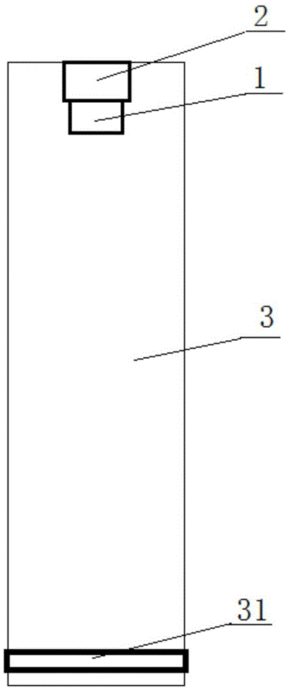
[0015] Such as figure 1 Shown is a structural schematic diagram of the acoustic wave water level gauge provided by the present invention. The device includes a sound wave transceiver 1 and a processor 2. The sound wave transceiver 1 is used to transmit and receive sound waves, and transmit them to the processor 2 for processing data. Specifically, the processor 2 is installed on the top of the acoustic wave transceiver 1, because the...


PUM


Abstract

The invention provides a sound wave water level gauge which comprises a sound wave transceiver and a processor. The transceiver and the processor are sleeved with an echo chamber. The inner wall of the echo chamber is provided with an annular reflection ring. According to the sound wave water level gauge, the transceiver and the processor are sleeved with the echo chamber, and the inner wall of the echo chamber is provided with the annular reflection ring, when a specific area is measured, all the components are installed in place, sound waves are sent out through the sound wave transceiver, and the sound waves are reflected through the reflection ring on the echo chamber; due to the fact that the certain distance is formed between the reflection ring and the sound wave transceiver, the sound waves are received by the sound wave transceiver and then calculated through the processor, accordingly, the propagation speed of a sound in the specific environment is figured out, the height of the water level is measured based on the speed, and more accurate data can be obtained.

Description

technical field [0001] The invention relates to the technical field of water level measurement, in particular to an acoustic wave water level gauge. Background technique [0002] The ultrasonic water level gauge is a digital liquid level instrument controlled by a microprocessor. In the measurement, the ultrasonic pulse is sent by the sensor (transducer), and the sound wave is reflected by the liquid surface and is received by the same sensor or ultrasonic receiver, which is converted into an electrical signal through a piezoelectric crystal or a magnetostrictive device, and is transmitted and received by the sound wave time to calculate the distance from the sensor to the surface of the liquid to be measured. Due to the use of non-contact measurement, the measured medium is almost unlimited, and can be widely used to measure the height of various liquids and solid materials. [0003] However, since the speed of sound varies with different environmental conditions such as ...

Claims


Application Information

Patent Timeline
IPC IPC(8): G01F23/296
CPCG01F23/2962
Inventor 杨盛
Owner CHONGQING DUOBANG TECH DEV
Learn More