
Radiation-emitting apparatus

A technology for emitting radiation and equipment, applied in the field of equipment that emits radiation, and can solve problems such as non-radiation emission

Active Publication Date: 2016-04-06
OSRAM OLED
View PDF5 Cites 1 Cited by
  • Summary
  • Abstract
  • Description
  • Claims
  • Application Information

AI Technical Summary

Problems solved by technology

However, in radiation-emitting devices according to the prior art, due to different states, no radiation is emitted in some regions of the radiating surface

Method used


Image

  • Radiation-emitting apparatus
  • Radiation-emitting apparatus
  • Radiation-emitting apparatus

Examples


Embodiment Construction

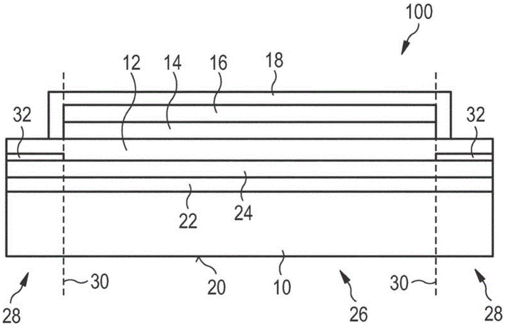
[0049] figure 1 A schematic cross-sectional view of a first exemplary embodiment of the radiation-emitting device, designated as a whole by the reference numeral 100 , is shown. The radiation-emitting device 100 includes a substrate 10 , for example a glass substrate. Furthermore, the radiation-emitting device 100 comprises a layer sequence comprising: an anode 12 serving as a first electrode surface; a cathode 16 serving as a second electrode surface; Between 16 is a functional layer 14 which is suitable for generating electromagnetic radiation in a certain wavelength range in the switched-on operating state. The encapsulation layer 18 protects the cathode 16 and the side surfaces of the functional layer 14 from external influences. Furthermore, the radiation-emitting device 100 includes a radiation-emitting surface 20 and a scattering layer 22 . A low-refractive layer 24 is also arranged between scattering layer 22 and anode 12 , the refractive index of which is lower tha...


PUM

PropertyMeasurementUnit
Diameteraaaaaaaaaa

Abstract

The invention relates to a radiation-emitting apparatus (100, 200), comprising: a substrate (10); at least one layer sequence, which is arranged on the substrate (10), is suitable for producing electromagnetic radiation in a wavelength range, and has at least one first electrode surface (12), at least one second electrode surface (16), and at least one functional layer (14) between the first electrode surface (12) and the second electrode surface (16), wherein the functional layer (14) is suitable for producing electromagnetic radiation in the wavelength range in a switched-on operating state; a radiation-emitting surface (20); and a diffusion layer (22) having a first region and a second region, wherein the diffusion layer (22) is designed to at least partially diffuse radiation incident on the first region of the diffusion layer (22) in such a way that said radiation enters the second region of the diffusion layer (22).

Description

technical field [0001] A device for emitting radiation is presented. [0002] This application claims priority from German patent application 102013108039.1, the disclosure of which is incorporated herein by reference. Background technique [0003] Radiation-emitting devices and in particular organic light-emitting diodes (OLEDs) are suitable as large-area, thin light-emitting elements. In many applications it is desirable for a device to emit electromagnetic radiation over the entire extent of its surface, the optical density of the radiation being as uniform as possible over the surface. However, in radiation-emitting devices according to the prior art, due to different states, no radiation is emitted in some regions of the radiating surface. This can be the case, for example, because these regions are covered by contact elements or insulating elements, or no radiation-emitting active layer is formed in these regions. [0004] In particular, OLEDs which are transparent ...

Claims


Application Information

Patent Timeline
IPC IPC(8): H01L51/52
CPCH10K50/854H10K50/856H10K50/858H10K2102/3031
Inventor 托马斯·韦卢斯约翰内斯·罗森伯格
Owner OSRAM OLED
Learn More