
Three-dimensional-map display system

A three-dimensional map and display system technology, which is applied in the directions of maps/plans/charts, image generation, image data processing, etc., can solve the problem that the position of self-view point cannot be visually identified, and achieve the effect of light load and reduced dead angle

Inactive Publication Date: 2016-04-06
GEO TECHN LAB
View PDF12 Cites 3 Cited by
  • Summary
  • Abstract
  • Description
  • Claims
  • Application Information

AI Technical Summary

Problems solved by technology

Since the three-dimensional map reproduces the state seen from the point of view, there will be blind spots that cannot be visually recognized from the point of view on underground structures such as tunnels or roads behind high-rise buildings.

Method used


Image

  • Three-dimensional-map display system
  • Three-dimensional-map display system
  • Three-dimensional-map display system

Examples


Embodiment 1

[0073] A. System composition:

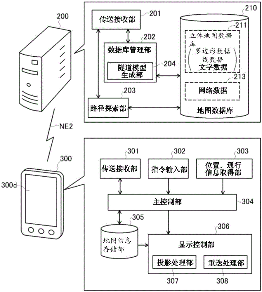
[0074] figure 2 It is an explanatory diagram of the configuration of the three-dimensional map display system. The three-dimensional map display system in this embodiment is used for route exploration, while displaying the three-dimensional Figure 1 edge path guidance. The three-dimensional map display system may not have the route search and route guidance functions, but only display the three-dimensional map based on instructions from the user or the like.

[0075] The three-dimensional map display system in the embodiment connects the server 200 and the terminal 300 through the network NE2. The terminal 300 may be a smartphone, but may also be various devices capable of displaying maps, such as a mobile phone, a portable information terminal, a personal computer, and a satellite navigation device. Furthermore, the three-dimensional map display system may be a system in which the server 200 and the terminal 300 are integrated.

[0076] ...

Embodiment 2

[0130] Next, the three-dimensional map display system in the second embodiment will be described. The second embodiment differs from the first embodiment in the data structure of the tunnels processed as permeable objects.

[0131] (1) Modification of tunnel data:

[0132] Figure 9 An explanatory diagram showing an example of the shape of tunnel data in the second embodiment. It shows the state of the tunnel that runs through the mountain approximately horizontally when viewed from the side. The upper part of the figure shows the topography, and the lower part shows a graph showing the depth D from the ground surface. The depth D represents the distance from the ground surface to the tunnel as shown in the above paragraph, and is positive when the tunnel is located underground.

[0133] In the figure, the curved ground surface that is convex upward is a mountain. The tunnel, shown below in solid lines, passes approximately horizontally. Since the ground surface is undul...


PUM


Abstract

To display a three-dimensional map in which planimetric features that cannot be seen, such as underground structures, can be expressed without imparting a sense of incongruity. Among a plurality of planimetric features stored in a map database, underground structures such as tunnels are categorized as transparent objects, and other planimetric features are categorized as non-transparent objects. Furthermore, the transparent objects and the non-transparent objects are respectively and separately projected to generate a transparent-object projection map and a non-transparent-object projection map. The degree of transparency is adjusted and the transparent-object projection map is superimposed upon the resultant non-transparent-object projection map. As a result of making the transparent-object side transparent and superimposing the transparent-object side, a map can be achieved in which a user can seemingly see the transparent objects, and see through the transparent objects to the planimetric features and the ground surface blocked thereby.

Description

technical field [0001] The present invention relates to a three-dimensional map display system capable of displaying a three-dimensional map by expressing unrecognizable features such as underground structures without a sense of incongruity. Background technique [0002] As an electronic map used on a satellite navigation device or a computer screen, there is a three-dimensional map that three-dimensionally represents features such as buildings. A three-dimensional map is generally drawn by projecting, for example, perspective projection of features arranged in a virtual three-dimensional space. Since the three-dimensional map reproduces the state seen from the point of view, there will be blind spots that cannot be visually recognized from the point of view on underground structures such as tunnels or roads behind high-rise buildings. [0003] In order to overcome the influence of blind spots, Patent Document 1 discloses a technique of drawing a tunnel with dashed lines or...

Claims


Application Information

Patent Timeline
Patent Type & Authority Applications(China)
IPC IPC(8): G06T17/05G06T11/60G09B29/00G09B29/10
CPCG01C21/3638G06T17/05G09B29/10G06T11/60G06T15/80G06T2210/62G06T2211/421G09B29/006G01C21/3635G06T19/003G09B29/005G09B29/106
Inventor 荒巻昌稔岸川喜代成手岛英治内海公志中上卓阿座上达也米仓达郎
Owner GEO TECHN LAB
Learn More