Intelligent shooting system alarming method, intelligent shooting system and network camera

A technology of network camera and camera system, applied in the field of intelligent camera system and network camera, can solve the problems of limited buzzer sound and single information of network camera, and achieve the effect of improving the degree of intelligence and the ability of information interaction

Inactive Publication Date: 2016-04-06
BEIJING QIHOO TECH CO LTD +1
View PDF4 Cites 14 Cited by
  • Summary
  • Abstract
  • Description
  • Claims
  • Application Information

AI Technical Summary

Problems solved by technology

[0006] The inventor found in the process of realizing the present invention that the information expressed by the network camera is very limited depending on the color of the indicator light, the flashing speed, the brightness, the synthetic sound type of the buzzer, the beeping speed and the size of the beeping sound; The information provided to the server is relatively simple; it can be seen that the intelligence of the existing camera system needs to be further improved

Method used


Image

  • Intelligent shooting system alarming method, intelligent shooting system and network camera
  • Intelligent shooting system alarming method, intelligent shooting system and network camera

Examples


Embodiment 1

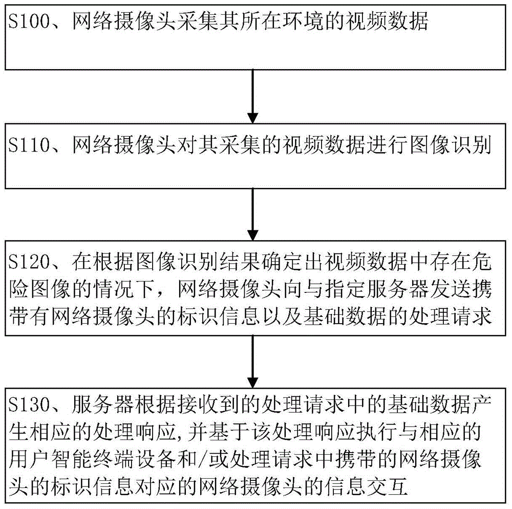
[0017] Embodiment 1, the alarm method of the intelligent camera system.

[0018] The intelligent camera system in the present embodiment mainly comprises: server and network camera, and a server is connected with one or more network cameras respectively; server connection. The server in this embodiment is also separately connected to a plurality of user intelligent terminal devices. For example, the user intelligent terminal devices are connected to the server through mobile communication technologies such as WIFI or GSM or CDMA or WCDMA.

[0019] The server in this embodiment may be a server set in the cloud, that is, a cloud server. The network camera in this embodiment may be a network camera integrated with a voice recognition function and an audio playback function. In addition, the above-mentioned user intelligent terminal device may be an intelligent electronic device such as a smart mobile phone, a desktop computer, a notebook computer, or a tablet computer, which ca...

Embodiment 2

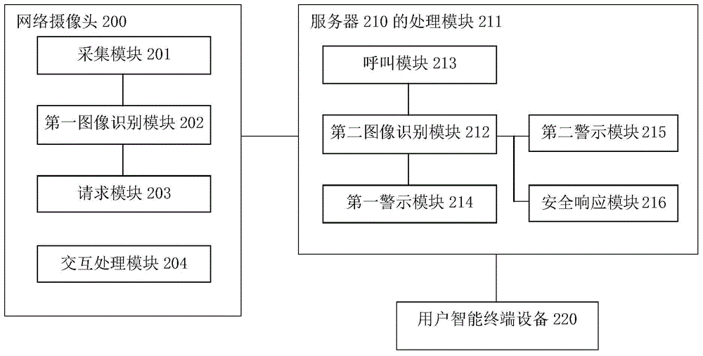
[0052] Embodiment 2, an intelligent camera system. Combine below figure 2 Each device included in the smart camera system of this embodiment and the specific structure of each device will be described in detail.

[0053] figure 2 The shown intelligent camera system mainly includes: a network camera 200 and a server 210 connected with the network camera 200; figure 2 It is only schematically shown that one network camera 200 is connected to the server 210 , but in actual application, one server 210 is usually connected to multiple network cameras 200 .

[0054] The network camera 200 can be connected to the server 210 through WIFI, and of course, the network camera 200 can also be connected to the server 210 through a wired connection. The server 210 in this embodiment is also connected to a plurality of user intelligent terminal devices 220 respectively ( figure 2 Only a user intelligent terminal device 220 is schematically shown in , for example, the user intelligent ...


PUM


Abstract

The invention discloses an intelligent shooting system alarming method, an intelligent shooting system and a network camera. The method comprises steps: the network camera acquires video data of the environment where the network camera is; the network camera carries out image recognition on the acquired video data; in a condition in which a dangerous image is determined to exist in the video data according to the image recognition result, the network camera sends a processing request carrying the identifier information of the network camera and basic data to a specified server, wherein the basic data comprise at least one selected from the dangerous image, audio data and the video data; and the specified server generates a processing response according to the basic data in the received processing request and executes information interaction with a corresponding user intelligent terminal device and / or the network camera corresponding to the identifier information of the network camera based on the processing response.

Description

technical field [0001] The invention relates to camera technology, in particular to an alarm method for an intelligent camera system, an intelligent camera system and a network camera. Background technique [0002] Some existing cameras can be connected to a server through a network, and a server can be connected to a large number of cameras, and users can call and view pictures captured by the cameras through the server. Such a camera may be called a webcam. [0003] The interaction between existing network cameras and users or servers usually includes the following two types: [0004] 1. The network camera notifies the user of the current status of the network camera through its indicator light or buzzer and other components. The status of the network camera usually includes: online, offline, started, viewed, abnormal alarm and crash, etc.; for example, for the Dropcam camera, the blue light is always on to indicate that the camera is currently online, the green light is...

Claims


Application Information

Patent Timeline
IPC IPC(8): H04N7/18G08B25/00
CPCG08B25/00H04N7/18
Inventor 沈海寅房文新王禾丰
Owner BEIJING QIHOO TECH CO LTD
Why Eureka
Try Eureka