A performance test method for receiving end

A technology of receiving end and performance, applied in the direction of receiver monitoring, etc., can solve the problem of large performance error of the test terminal, and achieve the effect of improving the accuracy

Active Publication Date: 2017-10-24
CHINA ACADEMY OF INFORMATION & COMM
View PDF4 Cites 0 Cited by
  • Summary
  • Abstract
  • Description
  • Claims
  • Application Information

AI Technical Summary

Problems solved by technology

[0006] In view of this, this application provides a method for testing the performance of the receiving end to solve the problem of large error in the performance of the test terminal in the indoor propagation environment

Method used


Image

  • A performance test method for receiving end
  • A performance test method for receiving end
  • A performance test method for receiving end

Examples


Embodiment Construction

[0018] In order to make the object, technical solution and advantages of the present invention clearer, the technical solution of the present invention will be described in detail below with reference to the accompanying drawings and examples.

[0019] The embodiment of the present application provides a receiving end performance testing method. In order to realize this solution, it is necessary to first establish an indoor channel model through a model building device. The channel model includes: indoor topology, the position of small base stations in the topology, and terminal movement path, and the speed at which the terminal moves.

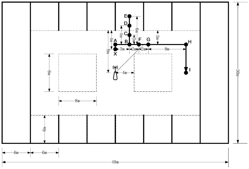
[0020] see figure 1 , figure 1 It is the indoor channel model established in the embodiment of this application. figure 1 The top view of the indoor topology in the indoor channel model established for .

[0021] in, figure 1 Solid lines represent load-bearing walls, and dashed lines represent non-load-bearing walls. The movement path of ...


PUM


Abstract

This application provides a receiver performance test method, which calculates the path loss in large-scale fading according to the distance between the terminal and the small base station, the distance between the terminal and the occluder in the indoor topology, and the carrier frequency, and obtains the shadow effect , and large-scale fading; the simulation device adds the large-scale fading determined under the channel model to perform link-level simulation, and obtains the throughput of the simulated receiving end in the link-level simulation; when it is necessary to perform a performance test of the receiving end indoors, Connect the channel simulator instrument between the sending end and the receiving end under test, add the large-scale fading determined under the indoor channel model through the channel simulator instrument, and obtain the throughput of the receiving end under test; compare the throughput of the receiving end under test and simulate the throughput of the receiving end to determine the performance of the receiving end under test in the indoor scene corresponding to the indoor channel model. Through this method, the accuracy of the performance test of the receiving end can be improved.

Description

technical field [0001] The invention relates to the technical field of wireless communication, in particular to a method for testing the performance of a receiving end. Background technique [0002] With the rise of the Internet of Things and Internet+, the coverage and capacity of wireless networks have become a hot spot of social concern. According to authoritative statistics, 70% of mobile network data services occur indoors. [0003] The early indoor coverage adopts the way of outdoor to indoor radiation, and the outdoor macro base station provides wireless services to indoor users with high power. Due to factors such as the penetration loss of signals entering the room from the outside and the refraction of indoor walls, this method can only provide basic voice services for users, but cannot provide stable high-speed data access indoors. Therefore, a new indoor distributed coverage method is introduced, and small-volume antennas are installed in different indoor locat...

Claims


Application Information

Patent Timeline
Patent Type & Authority Patents(China)
IPC IPC(8): H04B17/29
Inventor 张翔徐菲江甲沫魏贵明杜滢陈凯
Owner CHINA ACADEMY OF INFORMATION & COMM
Why Eureka
Try Eureka