Multi-modulus frequency divider and electronic device

一种多模分频器、多模分频的技术,应用在电气元件、脉冲计数器、产生/分配信号等方向,达到消除相位噪声、低功耗的效果

Active Publication Date: 2016-04-06
SEMICON MFG INT (SHANGHAI) CORP
View PDF5 Cites 5 Cited by
  • Summary
  • Abstract
  • Description
  • Claims
  • Application Information

AI Technical Summary

Problems solved by technology

However, neither of the above two MMDs based on Div2 / 3 unit cascading can meet this requirement

Method used


Image

  • Multi-modulus frequency divider and electronic device
  • Multi-modulus frequency divider and electronic device
  • Multi-modulus frequency divider and electronic device

Examples


Embodiment 1

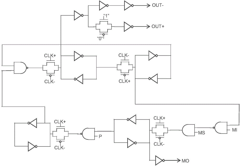
[0035] The embodiment of the present invention provides a new multi-mode frequency divider (MMD), which is an improved solution for the traditional MMD structure, and the frequency division coefficient is (2~2 N+1 -1) Continuously programmable. In order to meet the high-speed operation and low power consumption requirements of the multi-mode frequency divider at the same time, the embodiment of the present invention adopts a "divided by 2 / divided by 3 frequency divider" (DIV23 for short) based on "pseudo-differential" CMOS logic as the frequency division module unit circuit. Add a mode stop (ModeStop; MS) input terminal to the unit circuit using a divide-by-2 / divider-by-three frequency divider (DIV23), and use a certain combination of logic to control and close unnecessary flips of the divide-by-two / divider-by-three frequency divider unit , so while reducing power consumption, the additional spectral spurious components generated by the frequency divider can be reduced.

[0...

Embodiment 2

[0053] An embodiment of the present invention provides an electronic device, which includes an electronic component and a multi-mode frequency divider electrically connected to the electronic component. Wherein, the multi-mode frequency divider is the multi-mode frequency divider described in the first embodiment.

[0054] Exemplarily, the multimode frequency divider includes a frequency division module, a frequency selection module and a retiming module, and the frequency division module is used for performing multimode frequency division processing on the input signal and inputting the generated multiple frequency division signals To the frequency selection module, the frequency selection module is used to select the frequency division signal of the desired frequency from the multiple frequency division signals and input it to the retiming module, and the retiming module is used to The frequency division signal input from the frequency selection module performs retiming proc...


PUM


Abstract

The invention provides a multi-modulus frequency divider and an electronic device, which relate to the field of frequency dividing technologies. The multi-modulus frequency divider comprises a frequency division module, wherein the frequency division module comprises N divide-by-2 / 3 frequency divider units which are differentially cascaded, and each divide-by-2 / 3 frequency divider unit is composed of a high-speed differential D trigger based on CMOS logic. Therefore, the multi-modulus frequency divider can operate at a radio frequency and has low power consumption; in addition, the multi-modulus frequency divider comprises a retiming module 13, thus can eliminate phase noise to certain extent. The electronic device adopts the multi-modulus frequency divider, thus has the same advantages as the multi-modulus frequency divider.

Description

technical field [0001] The invention relates to a frequency division technology, in particular to a multi-mode frequency divider and an electronic device. Background technique [0002] A multi-mode frequency divider (Multi-Modulus Divider; MMD) is an important way to realize frequency division in a traditional phase-locked loop (phase-locked loop; PLL) technology. The multi-mode frequency divider circuit includes multiple cascaded frequency division units (for example: divide by 2 / divide by 3 frequency divider, referred to as DIV2 / 3), and generate corresponding output frequency according to the input frequency and frequency division coefficient (divisor) . [0003] The basic MMD structure has a continuous divider range of 2 N ~2 N+1 -1. For some mixed logic circuits, the range of extended divider ratios can reach 2 N-M ~2 N+1 -1. [0004] MMD based on Div2 / 3 unit cascading is currently divided into two specific implementation methods: [0005] The first is the differ...

Claims


Application Information

Patent Timeline
Patent Type & Authority Applications(China)
IPC IPC(8): H03K23/66
CPCH03K21/026G06F1/08H03K21/00H03K21/023H03K21/38H03K23/00H03K23/586H03L7/193H03L7/1974
Inventor 贾海珑
Owner SEMICON MFG INT (SHANGHAI) CORP
Why Eureka
Try Eureka