Cavity filter and cavity duplexer

A cavity filter and cavity duplexer technology, which is applied to waveguide-type devices, circuits, electrical components, etc., can solve the problems of increased manual debugging costs, influence of duplexer reliability, inconvenient system integration, etc. The effect of manual debugging cost, full use of space, and reduction of plane occupied area

Active Publication Date: 2018-09-14
COMBA TELECOM SYST (GUANGZHOU) LTD +1
View PDF5 Cites 0 Cited by
  • Summary
  • Abstract
  • Description
  • Claims
  • Application Information

AI Technical Summary

Problems solved by technology

Because of the requirements of high rejection and low transmission loss, cavity filters and duplexers are widely used in outdoor transceivers. The filters used are generally fundamental mode cavity filters, which have a large number of resonant cavities and are arranged in a plane. (Usually requires 6 or more resonant cavities), even if the coaxial structure is adopted, the occupied area is large, especially in the unfolded plane, which is not convenient for system integration and becomes one of the main bottlenecks restricting the miniaturization of the system
On the other hand, for traditional filters and duplexers, due to the relatively narrow bandwidth, the inevitable processing tolerances between multiple resonant cavities generally need to be debugged through tuning screws. Therefore, the duplexer The reliability will be affected, and the cost of manual debugging will be increased

Method used


Image

  • Cavity filter and cavity duplexer
  • Cavity filter and cavity duplexer
  • Cavity filter and cavity duplexer

Examples


Embodiment Construction

[0032] Embodiments of the present invention are described in detail below in conjunction with accompanying drawings:

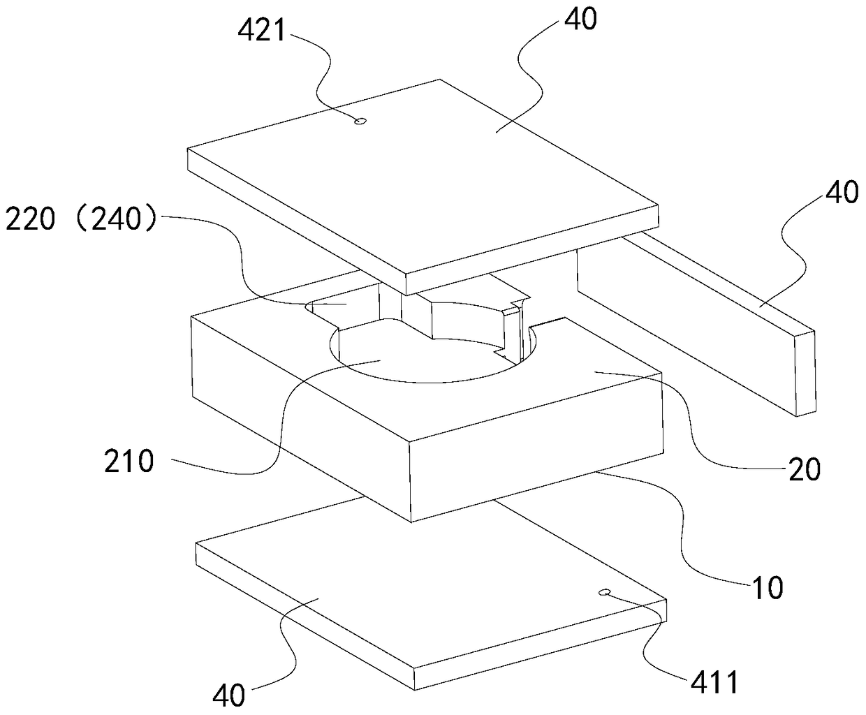
[0033] like Figure 1 to Figure 3 As shown, a cavity filter includes a first cavity shell 10 provided with a first resonant cavity 110, a second cavity shell 20 provided with a second resonant cavity 210, and the first resonant cavity 110 and the second resonant cavity are connected. The coupling channel 240 of 210, the cover plate 40 that seals the first resonant cavity 110 and the second resonant cavity 210, the first cavity shell 10 is provided with the input port 120 communicating with the first resonant cavity 110, the second cavity shell 20 is provided with and The output port 220 connected to the second resonant cavity 210, the first cavity shell 10 is arranged on the second cavity shell 20, and there is an angle α between the second cavity shell 20, where α=0°, the first cavity, At least one of the second resonant cavities is a dual-mode resonant cavi...


PUM


Abstract

The invention relates to a cavity filter and a cavity duplexer. The cavity filter comprises a first cavity shell, a second cavity shell, a coupling channel and a cover plate, wherein a first resonant cavity is formed in the first cavity shell; a second resonant cavity is formed in the second cavity shell; the coupling channel is used for communicating the first resonant cavity with the second resonant cavity; the cover plate is used for sealing the first resonant cavity and the second resonant cavity; an input port communicated with the first resonant cavity is formed in the first cavity shell; an output port communicated with the second resonant cavity is formed in the second cavity shell; and the first cavity shell is arranged on the second cavity shell, and an inclined angle alpha is formed between the first cavity shell and the second cavity shell, wherein alpha is greater than or equal to 0 degrees and less than or equal to 180 degrees. The inclined angle is formed between the first cavity shell and the second cavity shell, so that a foldable structure is formed; the first cavity shell and the second cavity shell are not arranged on the same plane, so that the planar occupied area is reduced; the cavity shells can be even molded with a machine case or other modules together, so that the system integration can be implemented conveniently, the space can be fully utilized, and the miniaturization of the system can be facilitated; compared with the conventional basic-mode cavity filter, the cavity filter provided by the invention is less in resonant cavities and higher in resonance property; and the planar occupied area of the cavity filter can be even reduced by more than 50%.

Description

technical field [0001] The invention relates to the technical field of microwave communication, in particular to a cavity filter and a cavity duplexer. Background technique [0002] Microwave communication is one of the most commonly used wireless communication methods in the world, and it is widely used in data transmission, mobile communication and other fields. With the increasing demand for microwave communication, the point-to-point or point-to-multipoint communication network composed of microwave antennas is becoming more and more dense, and the potential risk of mutual interference between microwave systems is increasing. Therefore, the number of equipment used in the communication network should be as small as possible, and at the same time, the miniaturization requirements for outdoor transceivers are also getting higher and higher. Because of the requirements of high rejection and low transmission loss, cavity filters and duplexers are widely used in outdoor tran...

Claims


Application Information

Patent Timeline
Patent Type & Authority Patents(China)
IPC IPC(8): H01P1/207H01P1/208
CPCH01P1/207H01P1/208H01P1/2082
Inventor 姜汝丹汪波赵兴
Owner COMBA TELECOM SYST (GUANGZHOU) LTD
Why Eureka
Try Eureka