Ka-waveband microstrip line gain equalizer

A gain equalizer, microstrip line technology, applied to the circuit components of transit time type electron tubes, etc., can solve the problems of increasing the difficulty of system integration, deteriorating circuit reliability, and occupying a large area, and achieving excellent standing wave performance, The effect of compact structure and large amount of single-stage equalization

Active Publication Date: 2016-04-06
10TH RES INST OF CETC
View PDF5 Cites 5 Cited by
  • Summary
  • Abstract
  • Description
  • Claims
  • Application Information

AI Technical Summary

Problems solved by technology

To achieve a large amount of equalization, multi-level cascading is required, which takes up too much area, increases the difficulty of system integration, deteriorates the reliability of the circuit, and brings a lot of inconvenience to the application.

Method used


Image

  • Ka-waveband microstrip line gain equalizer

Examples


Embodiment Construction

[0013] The present invention will be further described below in conjunction with drawings and embodiments.

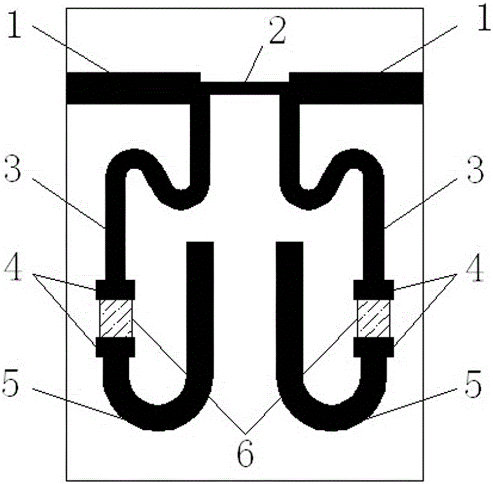
[0014] refer to figure 1 . In the embodiment described below, a Ka-band microstrip line gain equalizer includes two sections of 50Ω microstrip line 1, impedance matching microstrip line 2, high-impedance microstrip line 3, widened microstrip line 4, microstrip line With open circuit stub 5 and thin film resistor 6. A high-resistance microstrip line 3 is set between the thin film resistor 6 and the main transmission line, and a wider microstrip open branch 5 is behind the thin film resistor 6 . The high-resistance microstrip line 3 is bent into an S shape, and the microstrip open stub 5 is bent into a U shape. The actual thin film circuit size of this embodiment is 2.9mm×3.7mm.

[0015] The main microwave signal transmission line is composed of an impedance matching microstrip line 2 in the middle and two 50Ω microstrip lines 1 on both sides. Both sides of the imped...


PUM


Abstract

The invention proposes a Ka-waveband microstrip line gain equalizer, and aims to provide an equalizer which is compact in structure and can be used for achieving high equilibrium quantity and improving amplitude-frequency response of a transceiving front end. The Ka-waveband microstrip line gain equalizer is implemented according to the following scheme: two segments of 50-ohm microstrip lines (1) are connected respectively from horizontal ports of T-shaped joints at the two sides of an impedance matching microstrip line (2) to form a main transmission line and also serve as an input end and an output end of a microwave signal; two microwave resonant units axially symmetric to each other along a vertical central line comprise high-resistance microstrip lines (3), widened microstrip lines (4), thin-film resistors (6) and microstrip open-circuit branches (5) which are sequentially connected and are loaded at vertical ports of the T-shaped joint at the two sides of the impedance matching microstrip line (2), the high-resistance microstrip lines (3) downwards extend from the T-shaped joint and extend towards a horizontal outer side and also are bent to an S shape, and the microstrip open-circuit branches (5) are bent towards a horizontal inner side to a U shape. By the Ka-waveband microstrip line gain equalizer, the problems of large area, difficulty in integration, low reliability, small single-stage equilibrium quantity and the like of the prior art are solved.

Description

technical field [0001] The invention relates to a Ka-band microstrip line gain equalizer that can be widely used to improve the amplitude-frequency response of a radio frequency transceiver front end. Background technique [0002] Broadband transceiver front-ends are widely used in satellite communication, phased array radar, electronic countermeasures and other missile-borne and airborne application systems that require miniaturization, especially in the high-total-gain transmit front-end that needs to integrate multi-stage amplifiers, mixers and filters Devices such as devices, and the device gain has inherently different frequency response characteristics in the working frequency band. After multi-stage accumulation, it often causes the entire front-end to inevitably have large gain fluctuations in the working frequency band, which cannot meet the requirements of in-band gain flatness. Requirements, bring a lot of inconvenience to the application. In order to solve this ...

Claims


Application Information

Patent Timeline
Patent Type & Authority Applications(China)
IPC IPC(8): H01J23/18H01J23/20
CPCH01J23/18H01J23/20
Inventor 李光
Owner 10TH RES INST OF CETC
Why Eureka
Try Eureka