Optical element thermal stress assessment system in vacuum environment

A technology of optical components and vacuum environment, which is applied in the fields of optical devices, optical radiation measurement, scientific instruments, etc.

Inactive Publication Date: 2016-04-06
CHANGCHUN INST OF OPTICS FINE MECHANICS & PHYSICS CHINESE ACAD OF SCI
View PDF5 Cites 2 Cited by
  • Summary
  • Abstract
  • Description
  • Claims
  • Application Information

AI Technical Summary

Problems solved by technology

[0005] In order to solve the problem of evaluating the thermal stress of optical components in a vacuum environment, the present invention provides a thermal stress evaluation system for optical components in a vacuum environment, and the system can further evaluate the effect of the temperature control device for optical components

Method used


Image

  • Optical element thermal stress assessment system in vacuum environment

Examples


Embodiment Construction

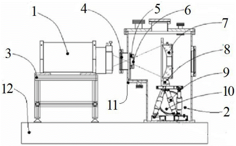
[0018] Such as figure 1 As shown, a thermal stress evaluation system for optical components in a vacuum environment, which includes an interferometer 1, a vacuum tank 2, a support frame 3, a glass window 4, a quartz heating tube 5, a quartz heating tube fixing seat 6, an optical component 7. Support structure 8, six degrees of freedom adjustment platform 9 and steps 11.

[0019] The interferometer 1 is placed on the support frame 3, and the support frame 3 is a five-degree-of-freedom adjustment mechanism, which can realize the adjustment of the five-degree-of-freedom of the interferometer 1 except rotation.

[0020] The support frame 3 and the vacuum tank 2 are placed on an optical platform 12 with a vibration isolation effect. The upper part of the vacuum tank 2 is provided with a step 11, the glass window 4 is arranged on the outer surface of the step 11, the quartz heating tube 5 is fixed on the quartz heating tube fixing seat 6, the quartz heating tube fixing seat 6 is ar...


PUM


Abstract

An optical element thermal stress assessment system in a vacuum environment belongs to the optical element thermal stress control related technology field. In order to solve the problem of assessing a thermal stress of an optical element in a vacuum environment, thermal radiation of a quartz heating pipe of the system is radiated on an optical element; the temperature and the shape of the surface of the optical element are measured through a window glass by using a non-contact infrared thermometric indicator and an interferometer in different time; and the shape change amount corresponding to different temperature changes are recorded, therefore, the thermal stress of the optical element is assessed in the vacuum environment. According to the invention, a heating pipe that employs a uni-chrome reflecting layer as a light source, therefore, ineffective heat radiation is prevented from thermal radiating an optical element support and other mechanical structures; the measurements of the temperature and shape are non-contact, therefore the change of the shape of the optical element can be reflected in real along with the change of the temperature in heat radiation.

Description

technical field [0001] The optical element thermal stress evaluation system involved in the present invention is mainly used for evaluating the surface shape change of the optical element when it is subjected to thermal radiation in a vacuum environment, and belongs to the technical field of optical element thermal stress control. Background technique [0002] When the optical element is irradiated by the light source, the temperature will rise accordingly, and its surface shape will change under the influence of thermal stress. Heat dissipation of optical components in a vacuum environment Without the help of an external temperature control system, the thermal stress of the optical components will cause great changes in the surface shape of the components, and even damage the optical components, which cannot meet the requirements of use. Therefore, in a vacuum environment Under the circumstances, if the optical element is strongly radiated by an external heat source, temper...

Claims


Application Information

Patent Timeline
Patent Type & Authority Applications(China)
IPC IPC(8): G01B11/24G01J5/00
CPCG01B11/2441G01J5/00
Inventor 周烽王辉郭本银谢耀王丽萍
Owner CHANGCHUN INST OF OPTICS FINE MECHANICS & PHYSICS CHINESE ACAD OF SCI
Why Eureka
Try Eureka