Clamping plate type reinforcing cage mounting platform

A technology for installing platforms and steel cages, applied in construction, infrastructure engineering, etc., can solve problems such as high construction safety risks, large construction safety risks, and difficult operations, achieve safe and reliable construction conditions, improve construction quality, and avoid human deviations Effect

Active Publication Date: 2016-04-06
ROAD & BRIDGE SOUTH CHINA EINGINEERING CO LTD +1
View PDF7 Cites 1 Cited by
  • Summary
  • Abstract
  • Description
  • Claims
  • Application Information

AI Technical Summary

Problems solved by technology

However, for heavy reinforcement cages, the operation safety is not high and it is not conducive to the development and progress of construction technology
[0006] The above two methods require manual operation to pass through the steel cage, so the degree of mechanization and automation is low, the work efficiency is low, and the risk of construction safety is high.
Especially when the design weight of the pile foundation reinforcement cage is large and the reinforcement spacing is small, it is difficult to install the reinforcement cage using the above two methods
If the steel bar is not damaged and the smaller section steel is used, it needs to be strengthened, and the steel cage can be installed after the force is satisfied, but the operation is still relatively difficult, and there is a high construction safety risk

Method used


Image

  • Clamping plate type reinforcing cage mounting platform
  • Clamping plate type reinforcing cage mounting platform
  • Clamping plate type reinforcing cage mounting platform

Examples


Embodiment 1

[0044] Clamp type reinforcement cage installation platform

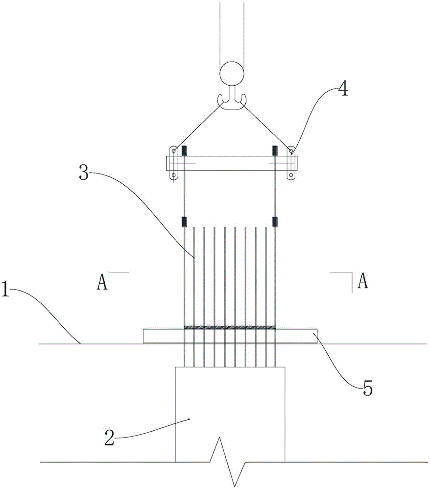
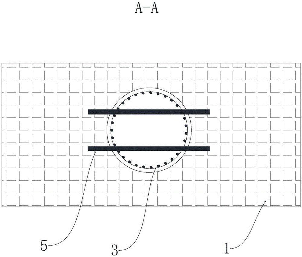
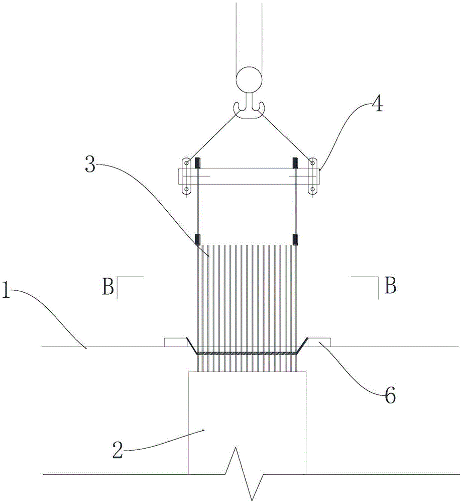
[0045] refer to Figure 5-8 In the present invention, the installation platform 7 of the clasp-type reinforcement cage includes an annular runner platform 71 and a clasp system 72 clamped on the annular runner platform 71 . The clip-type reinforcement cage installation platform 7 is placed on the construction platform 1 of the pile foundation, and is positioned at the corresponding pile foundation gap 11, so that the reinforcement cage 3 can be assembled and docked at the pile foundation gap 11.

[0046] refer to Figure 6 and 7, the annular runner platform 71 includes a main bracket 711 arranged around the pile foundation runner 11 and an annular plate 712 protrudingly installed on the main bracket 711 . The main support 711 includes a pair of first skeletons 7111 parallel to each other, a pair of second skeletons 7112 spanning between the first skeletons 7111, and the first skeletons 7111 and the second skeleton...

Embodiment 2

[0055] suspension system

[0056] refer to Figure 5 , the present invention lifts and lowers the reinforcement cage and its segments through the suspension system 4 . The suspension system 4 includes a hanger 41 and a hanging bar 42 whose top end is anchored to the hanger 41 . The hanging bars 42 are spliced ​​by multiple sections of steel bars, wherein the steel bars at the joints are tapped with external threads, and two adjacent sections of steel bars are connected by a steel bar extension connecting sleeve provided with internal threads. Further, the first section 421 of the hanging bar 42 is composed of two sections of steel bars, wherein the section anchored with the hanger 42 is the non-working section 4211, and the section anchored with the reinforcement cage 3 is the working section .

[0057] refer to Figure 14 , the suspension system 4 also includes a sand barrel 43 through the center drop frame, which is used to place the hanging ribs 42 passed through the up...

Embodiment 3

[0059] Installation method of super long and super heavy steel cage

[0060] refer to Figure 5 and Figures 15-19 , the installation method of the super-long super-heavy reinforcement cage of the present invention comprises the following steps:

[0061] 1. Install the steel cage installation platform

[0062] For large reinforcement cages, the assembly of reinforcement cages is generally carried out above or near the place where the reinforcement columns are installed, and the assembled reinforcement cages are lowered into the pre-placed reinforcement cage casing 2, so it can be installed according to the preset The position of the casing determines the placement position of the clamped steel cage installation platform 7 . Specifically, according to the central position of the pile foundation dragon mouth 11, the axis of the pile foundation is staked out, and the position of the central axis of the pre-assembled clamped steel cage installation platform 7 coincides with the...


PUM


Abstract

The invention discloses a clamping plate type reinforcing cage mounting platform. The clamping plate type reinforcing cage mounting platform comprises an annular gap platform and clamping plate systems which are arranged on the annular gas platform in a clamping manner, wherein the annular gap platform comprises a main bracket which is arranged circumferentially around a reinforcing cage and an annular plate which is mounted on the main bracket in a protruding manner; each of the clamping plate systems comprises a plurality of clamping plates which are arranged on the annular plate in a clamping manner; the direction towards the center of the annular plate is defined as the front direction; the clamping plates comprise plate bodies provided with front protruding angles and clamping slots which are formed in positions under the plate bodies and form front side surfaces and rear side surfaces. According to the clamping plate type reinforcing cage mounting platform disclosed by the invention, the integral construction of butting and positioning of extra-long overweight reinforcing cages is realized, the construction mechanized level and construction automatized level are effectively improved, and the construction operating environment is improved, so that the mounting operation of the reinforcing cage is safe, convenient and precise.

Description

technical field [0001] The invention relates to a road and bridge construction technology, in particular to a pallet-type reinforcement cage installation platform. Background technique [0002] Bridge engineering is widely used in highway engineering and railway engineering because of its advantages such as small footprint, small settlement, multiple structural forms, and wide application range. Pile foundations are the most common and widely used foundation form in bridge engineering. For some pile foundations with larger diameters and longer pile lengths, the weight of the reinforcement cage is relatively heavy and the spacing between the main reinforcements is relatively dense. than very difficult. [0003] In the prior art, the super-long and super-heavy reinforcement cages are installed in the following ways: [0004] refer to figure 1 and figure 2 One way is to suspend and install the reinforcement cage by crossing the section steel pole beam. There are many type...

Claims


Application Information

Patent Timeline
Patent Type & Authority Applications(China)
IPC IPC(8): E02D27/12
CPCE02D27/12
Inventor 肖向荣蔡东红刁先觉高世强檀兴华庞晓欣廖志方赵富立刘怀刚王文陈小华张铮葛纪平
Owner ROAD & BRIDGE SOUTH CHINA EINGINEERING CO LTD
Why Eureka
Try Eureka