Drill detection device used for qualitative detection of composition and distribution of soil layer

A technology of brazing and soil layer, which is applied in the field of basic soil survey, construction, infrastructure engineering, etc., can solve the problems of unnecessary, inconvenient to carry, inconvenient to carry equipment, etc., to reduce damage and impact, and to be easy to carry Effect

Inactive Publication Date: 2016-04-06
YULIN UNIV
View PDF6 Cites 1 Cited by
  • Summary
  • Abstract
  • Description
  • Claims
  • Application Information

AI Technical Summary

Problems solved by technology

At present, for the exploration of soil distribution below the ground, core drilling or physical excavation are commonly used to achieve. The conventional method takes a long time and has high economic costs. The equipment for core sampling is inconvenient to carry and needs the support of power supply equipment, which is difficult to meet Urgent needs of practical engineering
And in some projects, it is only necessary to roughly estimate the bearing characteristics of the soil. The traditional method can be used to evaluate the bearing characteristics of the soil more accurately, but it is not economical and unnecessary. It is an economical and fast device to find out the distribution of underground soil seems particularly necessary
The known method of finding out the distribution of soil below the ground takes a long time, costs a lot of manpower and financial resources and has the problem of inconvenient portability, and cannot quickly and economically find out the distribution of soil layers

Method used


Image

  • Drill detection device used for qualitative detection of composition and distribution of soil layer

Examples


Embodiment Construction

[0021] The present invention will be further explained below in conjunction with specific embodiments and accompanying drawings.

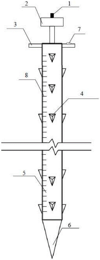
[0022] see figure 1 , the present invention includes a hollow drill rod 5, one end of the hollow drill rod 5 is fixedly provided with a thruster 2, the thruster 2 is a circular or rectangular pressing plate convenient for the operator to apply force, the thruster 2 is made of steel or iron, and The circular surface or rectangular surface is perpendicular to the hollow drill rod 5; the other end of the hollow drill rod 5 is fixedly provided with a tip 6 that is convenient to be pressed into the soil, and the tip 6 is set in a conical shape, and the hollow drill rod 5 is provided with a pressing rod. The barb 4 is arranged on the pressure rod, and the barb 4 is arranged in the shape of a triangular pyramid. The upper surface of the triangular pyramid is provided with a groove for taking soil, and the side wall of the hollow drill rod 5 is provided wi...


PUM


Abstract

The invention discloses a drill detection device used for qualitative detection of the composition and distribution of a soil layer. By the adoption of the drill detection device used for qualitative detection of the composition and distribution of the soil layer, the distribution condition of the soil layer can be known rapidly and economically, real-time and economical stratum data can be provided for actual engineering, important data are provided for judging the soil bearing capacity, and the drill detection device has guidance and application significance for the actual engineering. According to the technical scheme, the drill detection device used for qualitative detection of the composition and distribution of the soil layer comprises a hollow drill rod (5); a thruster (2) is fixedly arranged at one end of the hollow drill rod (5); the working surface of the thruster (2) is perpendicular to the axis of the hollow drill rod (5); a pointed end (6) which can be pressed into a soil body conveniently is fixedly arranged at the other end of the hollow drill rod (5); a pressing rod is arranged in the hollow drill rod (5); a plurality of barbs (4) are arranged on the pressing rod; holes used for allowing the barbs (4) to stretch out are formed in the side wall of the hollow drill rod (5); the barbs (4) are located inside the hollow drill rod (5) when pressed into the hollow drill rod (5); the barbs (4) are located outside the hollow drill rod (5) and can carry out soil samples when pulled out of the hollow drill rod (5).

Description

technical field [0001] The invention belongs to the technical field of soil layer detection, and in particular relates to a drilling device for qualitatively detecting the composition and distribution of soil layers. Background technique [0002] The distribution of soil layers is an important basis for evaluating soil bearing capacity. Quickly finding out the distribution of soil layers below the ground is of great value for evaluating soil bearing capacity in more urgent engineering sites, and has certain implications for survey work in actual projects. Guiding significance. At present, for the exploration of soil distribution below the ground, core drilling or physical excavation are commonly used to achieve. The conventional method takes a long time and has high economic costs. The equipment for core sampling is inconvenient to carry and needs the support of power supply equipment, which is difficult to meet The urgent need of practical engineering. And in some project...

Claims


Application Information

Patent Timeline
IPC IPC(8): E02D1/04
CPCE02D1/04
Inventor 鲍亮亮赵高文马小莉韦锋林勇勇童行伟
Owner YULIN UNIV
Why Eureka
Try Eureka