Laser template polishing clamp

A polishing fixture and laser template technology, applied in the electrolysis process, electrolysis components and other directions, can solve the problems of low production efficiency, long locking or loosening operation time, etc., and achieve the effect of high production efficiency, short operation time and easy operation.

Active Publication Date: 2016-04-06
SUZHOU SUNSHINE LASER & ELECTRONICS TECH CO LTD
View PDF4 Cites 3 Cited by
  • Summary
  • Abstract
  • Description
  • Claims
  • Application Information

AI Technical Summary

Problems solved by technology

[0005] The technical problem solved by the present invention: SMT laser template polishing fixture usually adopts screws

Method used


Image

  • Laser template polishing clamp
  • Laser template polishing clamp
  • Laser template polishing clamp

Examples


Embodiment Construction

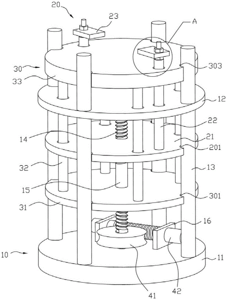
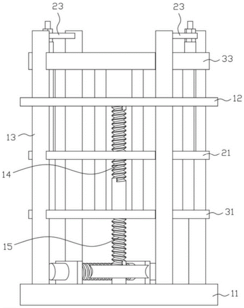
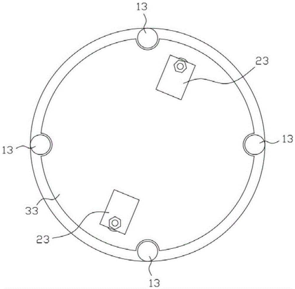
[0029] combine Figure 1 to Figure 3 , a laser template polishing fixture, including a bracket body 10, a locking body 20, and a fixing seat body 30.

[0030] Such as figure 1 , the support body 10 includes a base 11, a support plate 12, and a pillar 13; the pillar is vertically arranged on the base, and the support plate is horizontally arranged on the pillar.

[0031] Such as figure 1 , the locking body 20 includes a first lift chassis 21, a pair of first guide columns 22, and a locking block 23; the first lift chassis provides a first guide notch 201, and the first guide notch and the pillar Sliding fit; the pair of first guide posts are vertically arranged on the first lifting chassis, a pair of first guide holes are opened on the support plate, and a pair of first guide posts are matched in a pair of one-to-one manner. In the first guide hole; the locking block is installed on the top of the first guide post.

[0032] In the above-mentioned locking body 20, such as ...


PUM


Abstract

The invention discloses a laser template polishing clamp. The laser template polishing clamp comprises a support body, a locking body and a fixed seat. The support body comprises a base, supporting plates and supporting columns. The locking body comprises first base plates and lock blocks, wherein the first base plates and the lock blocks are connected through first guiding columns, and the first guiding columns penetrate the supporting plates. The fixed seat comprises second base plates and fixing discs, the second base plates and the fixing discs are connected through second guiding columns, the second guiding columns upward penetrate the first base plates and the supporting plates, and the lock blocks are located above the fixing discs. The support body comprises threaded rods different in vertical screwing direction. The upper sections and the lower sections of the threaded rods are in screw joint with the first base plates and the second base plates respectively. Worms and gears are arranged at the bottoms of the threaded rods. The worms and gears drive the first base plates to drive the lock blocks to descend through driving of the threaded rods, meanwhile, the second base plates are driven to drive the fixing discs to ascend, accordingly, workpieces on the fixing discs are vertically clamped through the fixing discs and the lock blocks, operation is easy and convenient, and production efficiency is high.

Description

Technical field: [0001] The invention relates to the technical field of SMT laser templates, in particular to a laser template polishing fixture. Background technique: [0002] In the process of SMT laser stencil production, when the stainless steel sheet is laser cut, there will be burrs and oxides on the hole wall, which will seriously affect the quality of SMT laser stencil printing solder paste and cannot meet customer requirements. In order to solve this problem, the hole wall of the steel sheet after laser cutting must be processed. The treatment method is electrochemical polishing process. In order to perform electrochemical polishing, a polishing jig must be used, and the laser-cut steel sheet must be mounted on the polishing jig, so that it can cooperate with the polishing equipment to complete the electrochemical polishing. [0003] In the existing SMT laser template manufacturing process, the fixture is usually fixed by screws. The disadvantage is that an additi...

Claims


Application Information

Patent Timeline
IPC IPC(8): C25F3/24C25F7/00
CPCC25F3/24C25F7/00
Inventor 王荣郭学亮
Owner SUZHOU SUNSHINE LASER & ELECTRONICS TECH CO LTD
Why Eureka
Try Eureka