
Vacuum packaging machine

A vacuum packaging machine, vacuum chamber technology, applied in packaging, packaging under vacuum/special atmosphere, transportation packaging, etc., can solve the problems of inability to meet the requirements of vacuum packaging, poor sealing effect of vacuum chambers, and inability to guarantee product quality, and achieve easy Airtight, improved packaging efficiency, easy rinse-off effect

Inactive Publication Date:
View PDF11 Cites 5 Cited by
  • Summary
  • Abstract
  • Description
  • Claims
  • Application Information

AI Technical Summary

Problems solved by technology

This vacuum chamber structure is suitable for small vacuum chambers. When the length of the vacuum chamber increases, the sealing effect of the vacuum chamber is poor and cannot meet the requirements of vacuum packaging. The vacuum degree is insufficient and the product quality cannot be guaranteed.

Method used


Image

  • Vacuum packaging machine
  • Vacuum packaging machine
  • Vacuum packaging machine

Examples


Embodiment Construction

[0026] Below in conjunction with accompanying drawing, the present invention is described in detail:

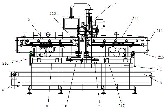
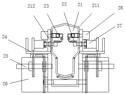
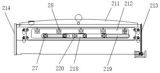
[0027] like figure 1 As shown, a vacuum packaging machine of the present invention includes a body 1 , a vacuum chamber device 2 and a feeding device 3 . There are two vacuum chamber devices 2 , which are distributed on both sides of the feeding device 3 . When working, the feeding device first feeds the vacuum chamber device on one side. After the packaging bag of the vacuum chamber device on one side is full, the vacuum chamber device on the side starts to vacuum and seal, and the feeding device feeds the vacuum chamber device on the other side. Room device feeding. The two vacuum chambers are alternately used for feeding, vacuuming and sealing, thus achieving a substantial improvement in packaging efficiency.

[0028] The structure of the vacuum chamber device 2 is as follows figure 2 , image 3 As shown, it includes a vacuum chamber 21 , a sealing chuck 22 , a seali...


PUM


Abstract

The invention discloses a vacuum packaging machine. The vacuum packaging machine comprises a machine body, a feeding device and vacuum chamber devices, wherein the feeding device and the two vacuum chamber devices are arranged on the machine body. Each vacuum chamber device comprises a vacuum chamber, a sealing clamping head and a plurality of sealing heads, wherein the sealing clamping head and the sealing heads are arranged inside the vacuum chamber. The feeding device comprises a transmission mechanism and feeding clamping heads arranged on the transmission mechanism at intervals and connected with a clamping air cylinder. The transmission mechanism is located between the two vacuum chamber devices. Each vacuum chamber device further comprises a driving mechanism used for enabling the corresponding sealing clamping head to clamp packages on the feeding clamping heads and sequentially feed the packages into each sealing head. Compared with the prior art, the feeding device and the two vacuum chamber devices are adopted, the multiple sealing heads used for sealing the packages are arranged in each vacuum chamber device, continuous operation of the feeding device is guaranteed through alternative feeding and sealing of the two vacuum chamber devices, and the packaging efficiency is improved.

Description

technical field [0001] The invention relates to a vacuum packaging machine, which belongs to the technical field of vacuum packaging. Background technique [0002] The existing vacuum packaging machine adopts a linear drive mechanism for feeding or adopts a rotary multi-station feeding and sealing integrated structure. The packaging efficiency of this structure is low. The vacuum chamber of this vacuum packaging machine generally adopts the structure of the vacuum front chamber and the vacuum back chamber. Among them, the vacuum front chamber is fixed, and the vacuum rear chamber is active. When the packaging bag is sealed, the vacuum back chamber is combined with the vacuum front chamber to form a vacuum chamber, and then the vacuum chamber is vacuum sealed. This vacuum chamber structure is suitable for small vacuum chambers. When the length of the vacuum chamber increases, the sealing effect of the vacuum chamber is poor, which cannot meet the requirements of vacuum pac...

Claims


Application Information

Patent Timeline
Patent Type & Authority Applications(China)
IPC IPC(8): B65B31/02B65B51/14
CPCB65B31/024B65B51/146
Inventor 李国华顾国进
Learn More