
Segmented shear type elastic wheel for rail transit vehicles

A technology for rail transit vehicles and elastic wheels, which is applied in the field of segmented shear elastic wheels, can solve problems such as the inability to realize common use of vibration damping elements, increase the development and manufacturing costs of wheels, etc., and achieve excellent vibration and noise reduction performance, The structure is simple and reasonable, and the effect of reducing the unsprung mass

Active Publication Date: 2017-12-29
CRRC CHANGZHOU TECH MARK IND CO LTD +1
View PDF1 Cites 0 Cited by
  • Summary
  • Abstract
  • Description
  • Claims
  • Application Information

AI Technical Summary

Problems solved by technology

However, the elastic body of the damping element in the above-mentioned shear elastic wheel scheme is an integral ring structure. When the diameter or shape interface of the wheel changes, it is necessary to redesign the mold and product for manufacturing the elastic body, and it is impossible to realize the vibration damping element in different Common use in wheels increases the development and manufacturing costs of wheels

Method used


Image

  • Segmented shear type elastic wheel for rail transit vehicles
  • Segmented shear type elastic wheel for rail transit vehicles
  • Segmented shear type elastic wheel for rail transit vehicles

Examples


Embodiment Construction

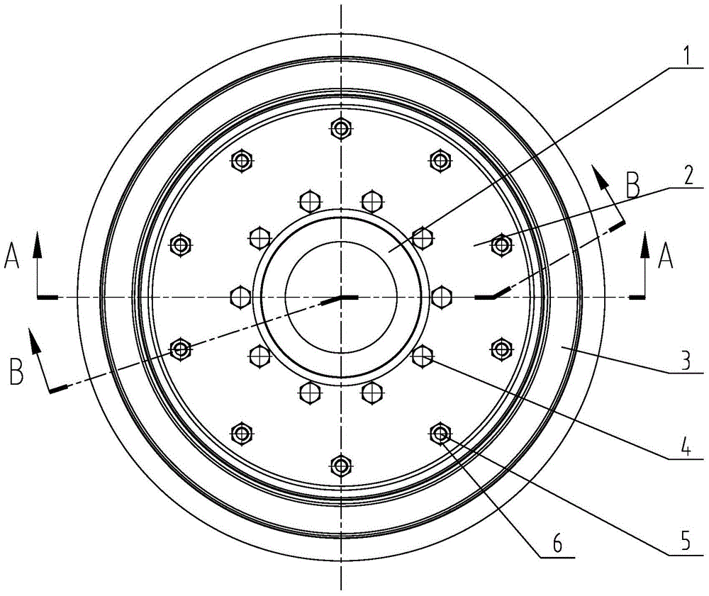
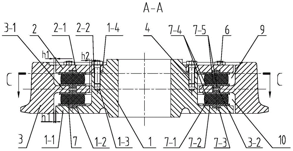
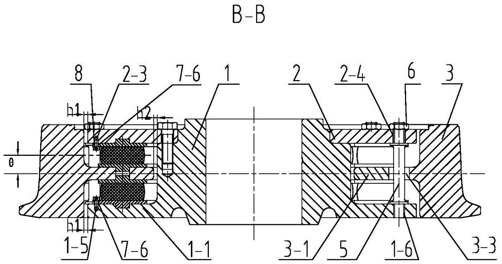
[0029] See Figure 1-7 As shown, the segmented shear type elastic wheel for rail transit vehicles of the present invention includes a wheel center 1, an annular pressure ring 2 and a tire 3 and is connected between the wheel center 1, the pressure ring 2 and the tire 3 of elastic body.

[0030] See Figure 1~4 As shown, the inner side of the wheel center 1 of the present invention has a wing plate 1-1, and the outer side has a mounting groove 1-4, and the pressure ring 2 is arranged at the mounting groove 1-4 of the wheel center 1 and is fixedly connected to the wheel center 1 by fasteners. ,See figure 2 , 3 As shown, the wheel center 1 of the present invention has an L-shaped structure along the cross-section of the center of rotation, and the end faces and outer circles of the mounting grooves 1-4 on the wheel center 1 are matched with the end faces and inner rings of the pressure ring 2, and are used to mount the pressure ring 2 Installed at the installation groove 1-4...


PUM


Abstract

The invention relates to a divided shear-type elastic wheel used for rail transit vehicles. The divided shear-type elastic wheel comprises a wheel core, an annular pressing ring and a strake. A wing plate is arranged on the inner side of the wheel core, and an installation groove is formed in the outer side of the wheel core. The pressing ring is fixedly connected with the wheel core through fasteners. A web of the strake is arranged between the pressing ring and the wing plate, and the space between the pressing ring and the wing plate is divided into a left annular cavity and a right annular cavity which are symmetrical. A plurality of elastic units are uniformly distributed in the left annular cavity and the right annular cavity in the circumferential direction, and the elastic units can not rotate in the left annular cavity and the right annular cavity. A radial deformation gap H1 is formed between the outer circle of the pressing ring and the hole wall of the strake as well as between the outer circle of the wing plate and the hole wall of the strake, and a radial deformation gap H2 is also formed between the inner circle of the web and the outer circle of the wheel core. The included angle theta between the central surface of each elastic block and the rolling plane of the strake ranges from 0 degree to 25 degrees. The divided shear-type elastic wheel used for the rail transit vehicles is reasonable in structure, high in modularization degree, convenient to assemble and maintain, capable of reducing the manufacturing cost and using cost, and high in vibration reduction performance and noise reduction performance and can be applicable to different wheel diameters.

Description

technical field [0001] The invention relates to a segmented shear type elastic wheel for rail transit vehicles, which belongs to the technical field of elastic wheels for light rail vehicles. Background technique [0002] As urban traffic problems become increasingly prominent, urban rail vehicles have become an important choice for urban traffic due to their advantages in economy, environmental protection, convenience, and comfort. The elastic wheel is a vibration-damping rubber embedded between the wheel rim and the wheel center. Relying on the vibration-damping effect of the rubber, it can reduce the impact noise of the wheel rail, ease the impact vibration of the wheel rail, and improve the passenger comfort. Existing elastic wheels can be divided into three types according to the bearing mode of the damping rubber: pressure-bearing type, shear type and compression-shear composite type. The rubber element of the pressure-bearing elastic wheel mainly bears the radial pre...

Claims


Application Information

Patent Timeline
Patent Type & Authority Patents(China)
IPC IPC(8): B60B17/00
CPCB60B17/0017B60B17/0041B60B17/0058B60B17/0068
Inventor 侯传伦戚援王慎潘勤涛宁烨
Owner CRRC CHANGZHOU TECH MARK IND CO LTD
Learn More