Linear type magnetic transmission device, screen printing system where linear type magnetic transmission device lies and using method

A magnetic transmission and linear technology, which is applied to screen printing machines, printing devices, printing, etc., can solve the problems of low transmission accuracy and low work efficiency, and achieve simplified mechanisms, high work efficiency, and reduced friction and noise Effect

Active Publication Date: 2016-04-06
武汉定达慧科技有限公司
View PDF7 Cites 5 Cited by
  • Summary
  • Abstract
  • Description
  • Claims
  • Application Information

AI Technical Summary

Problems solved by technology

[0005] The purpose of the present invention is to overcome the defects and problems of low transmission precision and low work efficiency in the prior art, and provide a linear magnetic transmission device with high transmission precision and high work efficiency. Screen printing system, and method of use

Method used


Image

  • Linear type magnetic transmission device, screen printing system where linear type magnetic transmission device lies and using method
  • Linear type magnetic transmission device, screen printing system where linear type magnetic transmission device lies and using method
  • Linear type magnetic transmission device, screen printing system where linear type magnetic transmission device lies and using method

Examples


Embodiment 1

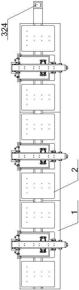
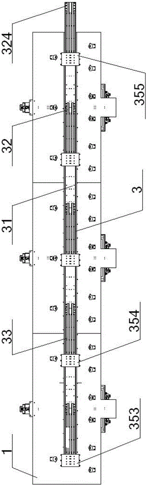
[0062] see figure 1 – Figure 12 , a linear magnetic transmission device, comprising a linear table 1 and a plurality of printing table 2 arranged on it, the printing table 2 rolls along the top surface of the linear table 1, and a printing table is arranged below the linear table 1 The linear driving device 3 of the plate 2; the linear driving device 3 includes a slide plate 31 and a plurality of electromagnetic coils 32, a linear guide rail 33, a rail seat 34, and a support seat 35, and the bottom of the electromagnetic coil 32 is connected to the top of the slide plate 31. The bottom surface of the slide plate 31 is connected with the top of the linear guide rail 33, the bottom of the linear guide rail 33 is slidably fitted with the guide rail seat 34 below it, the bottom of the guide rail seat 34 is connected with the bottom plate of the support seat 35, and the support seat 35 The side plate is connected with the linear table top 1; the electromagnetic coil 32 is evenly ...

Embodiment 2

[0066] Basic content is the same as embodiment 1, the difference is:

[0067] The support seat 35 is a U-shaped structure, including a seat bottom plate 351 and a seat side plate 352 vertically connected to its two ends, the top surface of the seat bottom plate 351 is connected with the bottom of the guide rail seat 34, and the seat side plate 352 is connected to the seat above it. Straight table 1 is connected. There are three rollers 24 in one printing platen 2 , wherein two rollers 24 are located on the same side of the permanent magnet 23 , and the other roller 24 is located on the other side of the permanent magnet 23 .

Embodiment 3

[0069] Basic content is the same as embodiment 1, the difference is:

[0070] see figure 1 – Figure 12 , the first two support seats 35 near the head end of the linear table top 1 on the linear drive device 3 are respectively the first support seat 353 and the first two support seats 354, and the support seat 35 at the tail end of the linear table top 1 is the rear support seat 355, the previous support base 353, the front two support bases 354 are respectively provided with the previous electromagnetic coil 321, the first three electromagnetic coils 323, the previous support base 353 is provided with the previous guide rail seat 341 to be consistent with the previous The linear guide rail 331 is slidably fitted, the head end of the preceding linear guide rail 331 is flush with the previous guide rail seat 341, and the top surface of the slide plate 31 directly above the tail end of the preceding linear guide rail 331 is connected with the first two electromagnetic coils 322...


PUM


Abstract

The invention discloses a linear type magnetic transmission device. The linear type magnetic transmission device comprises a plurality of printing platens and slide plates which are arranged above and below linear table boards, wherein the tops of the slide plates are provided with electromagnetic coils which are in one-to-one correspondence with permanent magnets connected to the bottoms of the printing platens; linear guide rails connected to the bottom surfaces of the slide plates are in sliding fit with guide rail bases arranged in supporting bases; the supporting bases are connected to the linear table boards; and two linear table boards and two arc-shaped table boards form an oval table board. In use, the slide plates drive the printing platens to roll and to move forwards on the linear table boards by virtue of attractive force between the electromagnetic coils and the permanent magnets; a distance every time the printing platens move is equal to a distance between adjacent two electromagnetic coils; and a turning type magnetic force transmission device on the arc-shaped table boards realizes turning of the printing platens on the arc-shaped table boards by virtue of mutual cooperation of a Z-shaped sub frame, a gear transmission mechanism and an L-shaped sub frame. The linear type magnetic transmission device is relatively high in precision, is relatively strong in cooperation, is relatively small in noise, is relatively low in operation difficulty, is relatively strong in controllability and is relatively high in working efficiency.

Description

technical field [0001] The present invention relates to a screen printing device, in particular to a linear magnetic transmission device, a screen printing system where it is located, and a method of use, which are particularly suitable for improving the accuracy of transmission and improving work efficiency. Background technique [0002] The characteristic of screen printing is to set up a screen frame for each color pattern. Affected by the flower pattern, due to the variety of colors, multiple screen frames must be equipped to complete the printing of a complete set of patterns, which requires one The printing table needs to be printed by multiple stations on the track surface. The process is complicated and there are many stations. It is simple, but the station is fixed and cannot be added at will. The drive of the elliptical orbit is more complicated, but the station is flexible, and stations can be added in the straight line according to the needs. Driven on the chain...

Claims


Application Information

Patent Timeline
Patent Type & Authority Applications(China)
IPC IPC(8): B41F15/14B41F15/08B41M1/12
CPCB41F15/08B41F15/14B41M1/12
Inventor 张智明徐巧祖耀殷先泽孙俊赵逸轩姬巧玲
Owner 武汉定达慧科技有限公司
Why Eureka
Try Eureka