
A kind of interlaminar fusion device

A fusion device and laminar technology, applied in the direction of spinal implants, etc., can solve the problems of inapplicability, inconvenient operation, spinal cord and nerve injury, etc., and achieve the effect of convenient operation

Active Publication Date: 2018-01-09
GENERAL HOSPITAL OF SOUTHERN THEATRE COMMAND OF PLA
View PDF11 Cites 0 Cited by
  • Summary
  • Abstract
  • Description
  • Claims
  • Application Information

AI Technical Summary

Problems solved by technology

[0004] However, in some cases, this kind of intervertebral fusion cannot solve the severe instability of the vertebral segment, and this kind of fusion needs to stretch the adjacent vertebral bodies to implant the fusion, which is not very convenient to operate
Even, sometimes the site to be operated on is not the adjacent vertebral body, but the separated vertebral body, and the fusion device mentioned above is even more inapplicable.
For these cases, bone grafting on the surface of the back of the lamina is often used clinically. Due to the existence of no compressive stress, the bone graft is easy to absorb, and the bone graft particles are scattered and may be displaced, resulting in spinal cord and nerve damage.

Method used


Image

  • A kind of interlaminar fusion device
  • A kind of interlaminar fusion device
  • A kind of interlaminar fusion device

Examples


Embodiment Construction

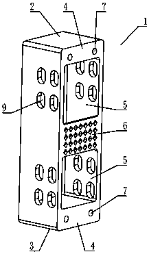
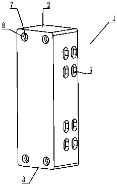
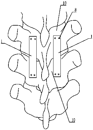
[0020] Such as figure 1 with figure 2 The interlaminar fusion device shown includes a connecting body 1, the connecting body 1 has an upper surface, a bottom surface, two side surfaces and two end surfaces, and the connecting body 1 also has a head 2, a tail 3, and the head 2 and the middle middle between. The head 2 and the tail 3 are respectively provided with connection surfaces 4, and the two connection surfaces 4 are located on the same side as the upper surface of the connecting body 1, and these connection surfaces 4 are used to connect and fix the surface on the same side of the lamina ,Such as image 3 shown. The middle part of the connecting body 1 is provided with an inner cavity for placing bone particles for induction, and the upper surface of the connecting body 1 is provided with a fusion port 5 communicating with the inner cavity, and the fusion port 5 is located between the two connecting surfaces 4 .

[0021] During the operation, bone particles for indu...


PUM


Abstract

The invention discloses a vertebral plate interbody fusion cage, comprising a connecting body. The head and the tail of the connecting body are respectively provided with a connecting surface. The connecting surfaces are on the same side with the upper surface of the connecting body. An inner cavity used to place bone grains is arranged between the head and the tail. The upper surface is provided with a fusion port communicating with the inner cavity. The fusion port is between the two connecting surfaces. The connecting surfaces which are on the head and on the tail and are on the same side are used to connect the surfaces of two different vertebral bodies on the same side. The bone grains used for induction are put in the inner cavity, and the bone grains grow out from the fusion port and fuse with vertebral plates, so as to complete fusion of two vertebral bodies and achieve an objective of treatment. Since the fusion cage connects the same-side surfaces of each vertebral plate and is not implanted in interbody, the fusion cage is suitable for fusion of adjacent vertebras, and fusion of vertebras at interval, and application is more convenient. The fusion cage can be used for vertebral plate interbody fusion.

Description

technical field [0001] The invention relates to the field of medical equipment and supplies, in particular to an interlaminar fusion device. Background technique [0002] Diseases such as lumbar disc herniation, lumbar instability, and spondylolisthesis often cause severe low back pain, and patients need lumbar fusion surgery. At present, in minimally invasive surgery, intervertebral fusion devices are generally used to fuse adjacent vertebral bodies, such as the "minimally invasive intervertebral fusion device" of CN101015477B, or the "minimally invasive lateral lumbar fusion device" of CN203555820U. [0003] The fusion devices mentioned above are all inserted into the gap between the two vertebral bodies from the head during operation, and the two intervertebral bodies are stretched apart. After that, the fusion devices are fixed and induced by bone particles in the fusion devices fusion. [0004] However, in some cases, this kind of intervertebral fusion device cannot s...

Claims


Application Information

Patent Timeline
Patent Type & Authority Patents(China)
IPC IPC(8): A61F2/44
CPCA61F2/4455
Inventor 马向阳邹小宝
Owner GENERAL HOSPITAL OF SOUTHERN THEATRE COMMAND OF PLA
Learn More