Attachment structure for deformation absorption member and attachment method
A technology of installation structure and installation method, which is applied in the direction of electrical components, collectors/separators, fuel cell parts, etc., and can solve problems such as large dimensional tolerances
- Summary
- Abstract
- Description
- Claims
- Application Information
AI Technical Summary
Problems solved by technology
Method used
Image

Examples
no. 1 Embodiment approach
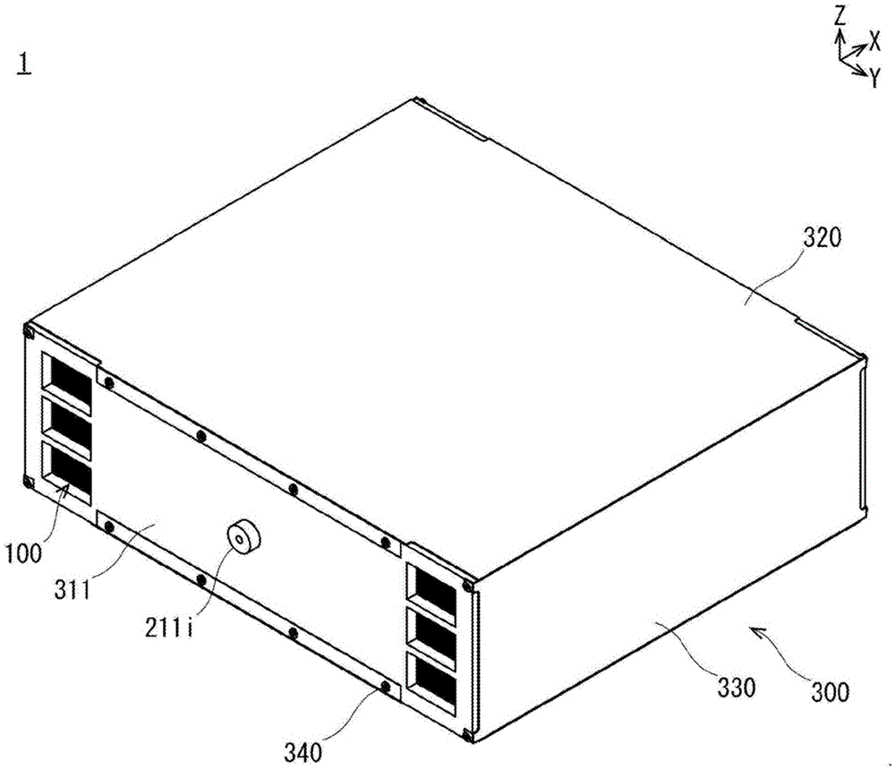
[0026] refer to Figure 1 to Figure 8 , the attachment structure and attachment method of the deformation absorbing member 20 of the first embodiment will be described.
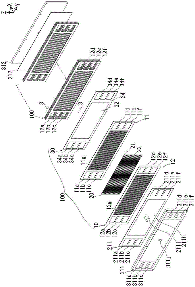
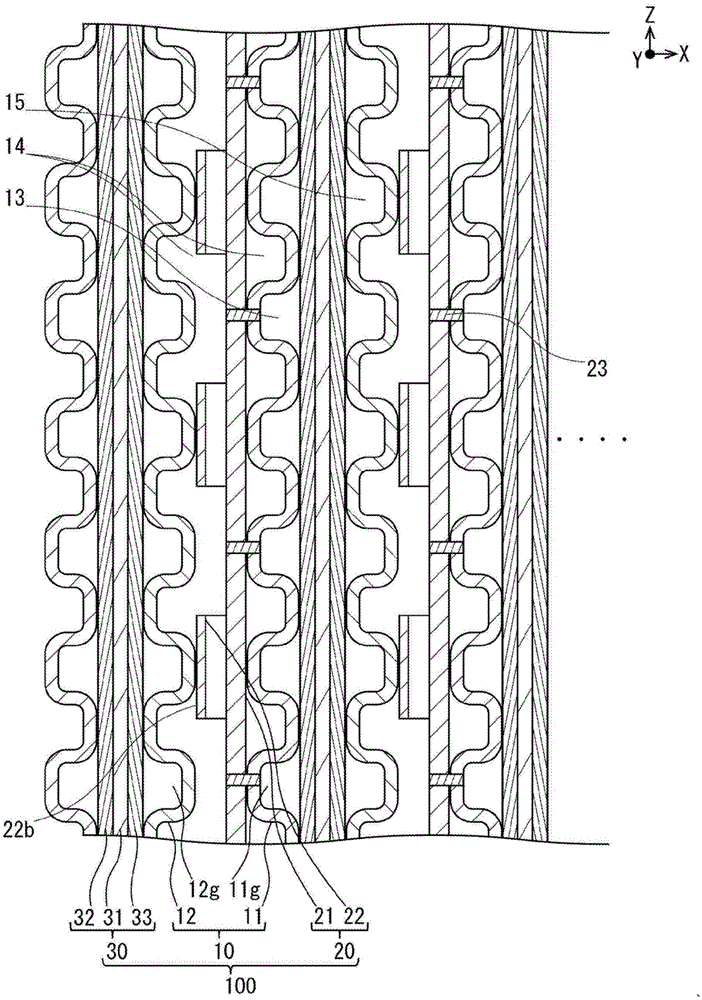
[0027] figure 1 It is a perspective view of the fuel cell 1 showing the mounting structure and mounting method of the deformation absorbing member 20 according to the first embodiment. figure 2 It is an exploded perspective view showing a part of the fuel cell 1 disassembled into each structural member. image 3 It is a partial sectional view showing the separator unit 10 , the deformation absorbing member 20 and the membrane electrode assembly 30 of the fuel cell 1 . image 3 along figure 2 The 3-3 lines are shown.
[0028] Figure 4 It is a perspective view showing the state of the deformation absorbing member 20 after being bonded to the separator unit 10 in the fuel cell 1 using a part of the deformation absorbing member 20 . Figure 5 It is a perspective view showing the state of the deformation...
no. 2 Embodiment approach
[0060] refer to Figure 9 and Figure 10 , the attachment structure and attachment method of the deformation absorbing member 40 of the second embodiment will be described.
[0061] Figure 9 It is a perspective view showing the state of the deformation absorbing member 40 after being bonded to the separator unit 10 in the fuel cell using a part of the deformation absorbing member 40 . Figure 10 It is a graph showing the characteristics of the deformation absorbing member 40 of the fuel cell.
[0062] Regarding the mounting structure and mounting method of the deformation absorbing member 40 of the second embodiment, the orientation of the extensions (free end portions 42 b ) of the raised pieces 42 arranged in a grid pattern is the same as that of two adjacent extensions in each row. The structure in which the directions are different from each other is different from the first embodiment described above.
[0063] In the second embodiment, the same reference numerals are...
no. 3 Embodiment approach
[0070] refer to Figure 11 and Figure 12 , the attachment structure and attachment method of the deformation absorbing member 50 of the third embodiment will be described.
[0071] Figure 11 It is a perspective view showing the state of the deformation absorbing member 50 after being bonded to the separator unit 10 in the fuel cell using a part of the deformation absorbing member 50 . Figure 12 It is a graph showing the characteristics of the deformation absorbing member 50 of the fuel cell.
[0072] The attachment structure and attachment method of the deformation absorbing member 50 of the third embodiment are different from those of the second embodiment in that the joint portions 53 of the raised pieces 52 provided in a lattice form are formed in a zigzag shape.
[0073] In the third embodiment, the same reference numerals are used for the same configurations as those in the above-mentioned first or second embodiment, and the above description is omitted.
[0074] ...
PUM
 Abstract
Description
Claims
Application Information
 - R&D
- Intellectual Property
- Life Sciences
- Materials
- Tech Scout
- Unparalleled Data Quality
- Higher Quality Content
- 60% Fewer Hallucinations
Browse by: Latest US Patents, China's latest patents, Technical Efficacy Thesaurus, Application Domain, Technology Topic, Popular Technical Reports.
© 2025 PatSnap. All rights reserved.Legal|Privacy policy|Modern Slavery Act Transparency Statement|Sitemap|About US| Contact US: help@patsnap.com