
LED lamp display and detection system

A technology of LED lamps and detection systems, applied in the direction of lamp circuit layout, lighting devices, light sources, etc., can solve the problems of high cost, high pertinence, and poor versatility, and achieve the effects of low production cost, strong versatility, and simple structure

Active Publication Date: 2016-03-30
广州中大中鸣科技有限公司
View PDF5 Cites 8 Cited by
  • Summary
  • Abstract
  • Description
  • Claims
  • Application Information

AI Technical Summary

Problems solved by technology

In the prior art, to realize automatic detection of LED lamps, LED lamps are generally designed as driver chips with feedback function, so that during the working process of LED lamps, their own parameters are regularly detected and fed back to the control system. This method High pertinence, it is necessary to configure a driver chip with feedback function in the LED lamp, resulting in high cost
Moreover, for the existing LED lighting system, automatic detection cannot be realized without replacing the driver chip, and the versatility is poor

Method used


Image

  • LED lamp display and detection system

Examples


Embodiment 2

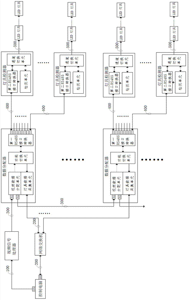
[0071] This embodiment is the control method of Embodiment 1, including:

[0072] LED lighting display steps, including:

[0073] The control computer sends video signals to the video signal processor through the digital video interface 101 and the video data line 100;

[0074] After the video signal processor receives the video signal, it sorts the video signal and converts it into lamp DMX protocol data processing, and then sends it to the video data distribution unit;

[0075] After receiving the DMX protocol data sent by the video signal processor, the video data distribution unit distributes the DMX protocol data to the first RS485 interface converter through the function switching unit, and transmits the DMX protocol data through the differential signal through the output port of the first RS485 interface converter. Line 400 is sent to the lamp detector;

[0076] The lamp detector receives the DMX protocol data through the second RS485 interface converter and converts ...


PUM


Abstract

The invention discloses an LED lamp display and detection system, which is used for controlling display content of an LED lamp and detecting working parameters of the LED lamp. The LED lamp display and detection system comprises a control computer, a video signal processor, a network switch, a plurality of data distributors and a plurality of lamp detectors, wherein a digital video interface of the control computer is connected with an input end of the video signal processor; an output end of the video signal processor is connected with the input ends of the plurality of data distributors respectively; the data distributors are connected with at least one lamp detector; and the control computer is connected with the plurality of data distributors through the network switch respectively. According to the LED lamp display and detection system, transmission of video data and detection data can be achieved; display control and detection feedback of the LED lamp are simultaneously achieved; an alarm is timely given when necessary; the LED lamp does not need to be provided with an individual feedback chip; and the LED lamp display and detection system is simple in structure, low in production cost and high in universality, and can be widely applied to the LED lamp industry.

Description

technical field [0001] The invention relates to the field of detection and control of LED lamps, in particular to a display and detection system for LED lamps. Background technique [0002] In the current technology, the function of the LED control system is limited to controlling and driving LED lamps, so as to display animation effects and realize synchronous playback of multiple LED lamps. With the continuous improvement of the demand for outdoor landscape lighting and the development of electronic information technology, more intelligent technology means are constantly integrated into the LED control system. Among them, the realization of the intelligent detection function of the lighting equipment enables the lighting system to intelligently judge the faulty lighting, locate the location of the fault, and notify the lighting maintenance personnel, especially in large-scale high-rise building lighting projects, greatly improving the work of lighting management and mainte...

Claims


Application Information

Patent Timeline
IPC IPC(8): H05B37/02H05B37/03
CPCH05B47/10H05B47/20
Inventor 陈邓伟陈建胜黄鑫辉祝亚森
Owner 广州中大中鸣科技有限公司
Learn More