Current transformer secondary open circuit protection method and device
A technology for current transformer and open-circuit protection, which is applied in the field of secondary open-circuit protection methods and devices for current transformers, can solve problems such as unfavorable promotion, troublesome operation, complicated structure, etc., so as to ensure timeliness and safety, simple equipment, and protection. Effects of circuits and current transformers
- Summary
- Abstract
- Description
- Claims
- Application Information
AI Technical Summary
Problems solved by technology
Method used
Image
Examples
Embodiment 1
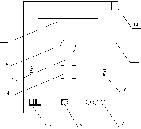
[0027] like figure 1 and figure 2As shown: the protection method of the present invention monitors the secondary side circuit voltage of the current transformer in real time through the secondary open circuit protection device of the current transformer. When the voltage is stable or fluctuates temporarily, it is considered normal. When the secondary side of the current transformer If the loop voltage rises and the delay is too long, the secondary side terminals of the current transformer are shorted by the secondary open circuit protection device of the current transformer. The brief fluctuation of the voltage means that the voltage does not exceed the safe voltage for 5 seconds, and the voltage rises and delays too long means that the voltage exceeds the safe voltage for 5 seconds. When the current transformer is not open circuit, the voltage on the secondary side is generally small at tens of volts. Once the secondary side is open circuited, the voltage will become very l...
Embodiment 2
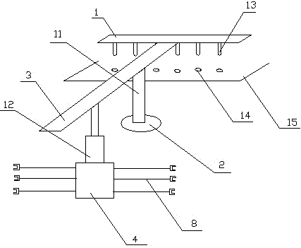
[0029] like figure 1 and figure 2 As shown: the present invention also provides a secondary open-circuit protection device for current transformers based on the above method, including a housing 9, a drive mechanism, a transmission mechanism and a short-circuit mechanism. The drive mechanism consists of a relay 2, an electric telescopic rod 12 and Connecting plug 8, the connecting plug 8 connects the relay 2 to the secondary side of the current transformer, the relay 2 is connected to the electric telescopic rod 12, the driving mechanism includes a base 2, and the base 2 passes through a bracket 11 A transmission rod 3 is set, one end of the transmission rod 3 is connected to the electric telescopic rod 12, the other end of the transmission rod 3 is connected to the short-circuit mechanism, the short-circuit mechanism includes a copper plate 1, and a plug 13 is arranged below the copper plate 1 , the copper plate 1 is wrapped with an insulating material. The connecting plug...
Embodiment 3
[0031] like figure 1 and figure 2 As shown: the present invention also provides a secondary open-circuit protection device for current transformers based on the above method, including a housing 9, a drive mechanism, a transmission mechanism and a short-circuit mechanism. The drive mechanism consists of a relay 2, an electric telescopic rod 12 and Connecting plug 8, the connecting plug 8 connects the relay 2 to the secondary side of the current transformer, the relay 2 is connected to the electric telescopic rod 12, the driving mechanism includes a base 2, and the base 2 passes through a bracket 11 A transmission rod 3 is set, one end of the transmission rod 3 is connected to the electric telescopic rod 12, the other end of the transmission rod 3 is connected to the short-circuit mechanism, the short-circuit mechanism includes a copper plate 1, and a plug 13 is arranged below the copper plate 1 , the copper plate 1 is wrapped with an insulating material. The connecting plug...
PUM
 Abstract
Description
Claims
Application Information
 - Generate Ideas
- Intellectual Property
- Life Sciences
- Materials
- Tech Scout
- Unparalleled Data Quality
- Higher Quality Content
- 60% Fewer Hallucinations
Browse by: Latest US Patents, China's latest patents, Technical Efficacy Thesaurus, Application Domain, Technology Topic, Popular Technical Reports.
© 2025 PatSnap. All rights reserved.Legal|Privacy policy|Modern Slavery Act Transparency Statement|Sitemap|About US| Contact US: help@patsnap.com


